← All 50 books
Book 30 of 50 · Free
ESP32 Projects for Beginners
25,021 words · 17 chapters · illustrated
Book 30 of 50 · Free
25,021 words · 17 chapters · illustrated
Book 30 of 50 — AstolixGen Learning Series For researcher and publication students
The ESP32 is the single most useful piece of hardware a researcher can learn in 2026 if your work touches sensing, measurement, automation, or the Internet of Things. It is a tiny, inexpensive microcontroller with built-in Wi-Fi and Bluetooth that you can program in the same Arduino language used by millions of hobbyists — and it is powerful enough to run real research prototypes: weather stations, air-quality monitors, smart-agriculture nodes, occupancy sensors, and data-logging experiments.
This book takes you from zero to a complete, working Wi-Fi sensor node that publishes real data. Every chapter follows the same pattern: you will understand why something works, wire it up, upload a complete working program (called a sketch), see exactly what should appear in the Serial Monitor, and learn how to fix it when it does not work. The chapters build on each other, so work through them in order.
You do not need prior electronics experience. You need an ESP32 development board (any common devkit), a USB cable that carries data (not a charge-only cable), a few jumper wires, a breadboard, a push button, and a DHT22 or DHT11 temperature/humidity sensor. Everything else is explained here.
Learning objectives:
Work the chapters in order — each assumes the previous one's working setup. A realistic pace is one chapter per sitting, two to three sittings per week:
Keep a lab notebook from Chapter 2 onward: wiring diagrams (phone photos are fine), library versions, error texts and fixes, and calibration constants. Researchers are distinguished from hobbyists less by what they build than by what they record.
By the end of this book, you will be able to:
The ESP32 is a family of low-cost, low-power microcontrollers designed by Espressif Systems, a company based in Shanghai. A microcontroller is a complete tiny computer on a single chip: it has a processor, memory, and input/output pins, but no operating system like your laptop. You load one program onto it, and it runs that program forever — reading sensors, switching things on and off, and talking to the internet.
The original ESP32 chip (released in 2016) contains two processor cores (a dual-core Xtensa LX6 running up to 240 MHz), about 520 KB of internal SRAM, built-in Wi-Fi and Bluetooth radios, and a rich set of peripherals: analog-to-digital converters (ADC), digital-to-analog converters (DAC), capacitive touch inputs, PWM outputs, and hardware support for common sensor protocols (I2C, SPI, UART). For perspective, that is roughly an order of magnitude more processing power and memory than the classic Arduino Uno's 8-bit ATmega328P running at 16 MHz with 2 KB of SRAM. The ESP32 is still a microcontroller, not a single-board computer like a Raspberry Pi — it cannot run Linux or a web browser — but for sensing and control tasks it is far more than enough.
Espressif has since released a whole family: the ESP32-S2 and ESP32-S3 (newer, USB-native, the S3 adds AI acceleration features), the ESP32-C3 and ESP32-C6 (RISC-V based, with the C6 adding newer Wi-Fi standards), and the ESP32-H2 (focused on low-power wireless protocols). When this book says "ESP32" without qualification, it means the original ESP32 or any devkit board based on the family — the Arduino code you will write works across them with only minor differences.
Beginners sometimes get confused by the three layers of "ESP32":
Any common ESP32 devkit board works with this book. Board layouts differ slightly between manufacturers (pin labels, which GPIO has the built-in LED), so every chapter includes a "check your board" reminder wherever a specific pin is named.
Five reasons the ESP32 shows up constantly in published IoT and sensing work:
setup() / loop() structure and the same libraries as an Arduino. The learning curve is gentle and the forum knowledge base is enormous.| Feature | Arduino Uno | ESP8266 | ESP32 |
|---|---|---|---|
| Processor | 8-bit, 16 MHz | 32-bit, 80/160 MHz | Dual-core 32-bit, up to 240 MHz |
| Memory (SRAM) | 2 KB | ~80 KB | ~520 KB |
| Wi-Fi | No (needs shield) | Yes | Yes |
| Bluetooth | No | No | Yes (Classic + BLE) |
| Analog inputs | 6 (10-bit) | 1 (10-bit) | Many (12-bit) |
| Typical use | Learning, simple control | Simple Wi-Fi projects | Sensing, IoT, research prototypes |
The ESP8266 (and its famous NodeMCU board) was the previous generation's favorite. It is still fine for the simplest Wi-Fi tasks, but the ESP32 costs nearly the same while offering more pins, more analog inputs, Bluetooth, two cores, and better power management. For any new project — and especially for research where you may add sensors later — choose the ESP32.
Every program you write in this book has the same skeleton:
void setup() {
  // Runs ONCE when the board powers on or resets.
  // Configure pins, start serial, connect Wi-Fi here.
}

void loop() {
  // Runs over and over, forever.
  // Read sensors, make decisions, send data here.
}
That is the entire mental model: setup() prepares, loop() repeats. Everything else in this book is detail hung on that frame. When your program misbehaves, the first diagnostic question is always: "Is the problem in setup() (it never starts correctly) or in loop() (it starts but does something wrong repeatedly)?"
ESP32 devkit boards expose general-purpose input/output pins labeled GPIO with a number (GPIO 2, GPIO 15, and so on). In code you refer to pins by these GPIO numbers, not by their physical position on the board. Two warnings that will save you hours across this book:
For your research: When you write up hardware in a paper's methodology section, never write just "an ESP32." Write the module (e.g., ESP32-WROOM-32), the devkit board name and manufacturer if known, the Arduino-ESP32 core version, and the exact GPIO-to-sensor mapping in a table. This is what makes your experiment reproducible — and reproducibility is what separates a demo from a publication.
It helps to know roughly what is on the silicon, because several later behaviors (ADC quirks, deep-sleep memory loss, dual-core options) follow directly from the hardware.
All of this is specified in Espressif's ESP32 Series Datasheet and Technical Reference Manual — the primary sources listed in this book's references. When in doubt about a hardware limit, the datasheet outranks any forum post.
Any common ESP32 devkit works, but these details affect your daily experience:
Three legitimate ways, in order of preference for beginners: (1) the USB port (5 V, easiest, powers everything including the 3.3 V regulator); (2) the VIN pin with a 5 V supply (for installations where USB is awkward); (3) the 3.3 V pin with a regulated 3.3 V source (advanced — bypasses the regulator, so your supply must be clean). Never feed 5 V into the 3.3 V pin or into a GPIO. For battery projects, start from Chapter 9's power math before choosing a cell.
A balanced introduction admits the boundaries — knowing them prevents doomed designs:
None of these disqualify the ESP32 for research sensing; they define where its competence ends and where your engineering begins.
Migration is mostly painless: WiFi, PubSubClient, and HTTPClient code ports almost unchanged, and GPIO numbers differ so check the pinout. What you gain: more analog inputs, Bluetooth, dual cores, touch pins, DAC, and proper deep-sleep options. What to unlearn: ESP8266's analogRead range is 0–1023 (10-bit) vs. ESP32's 0–4095 — scale any ported thresholds by 4, and re-test rather than assuming.
Key takeaways:
- The ESP32 is a dual-core 32-bit microcontroller with built-in Wi-Fi and Bluetooth, far more capable than an Arduino Uno and nearly the same price as the older ESP8266.
- Buy a devkit board (module + USB + regulator + pins); any common one works with this book.
- Every sketch is setup() once + loop() forever — learn that frame and every chapter fits into it.
- GPIO numbers are logical, not physical; check your board's labeling and avoid strapping/flash pins for general use.
Three pieces of software turn your computer into an ESP32 workstation:
You will also install libraries (reusable code packages) as chapters need them: the DHT sensor library in Chapter 5, PubSubClient in Chapter 7. Libraries are installed from inside the IDE, not downloaded by hand.
Download Arduino IDE 2.x from the official Arduino website (arduino.cc → Software) for your operating system and run the installer. Open it once to confirm it launches. You do not need an Arduino account.
The IDE learns about third-party boards from a JSON index file. Espressif publishes the official index; add it:
https://raw.githubusercontent.com/espressif/arduino-esp32/gh-pages/package_esp32_index.jsonThis URL is published in Espressif's official Arduino-ESP32 documentation. If you have other board URLs there already, separate them with commas.
Plug your ESP32 devkit into your computer with a data-capable USB cable. (This is the single most common setup failure: many cheap cables are charge-only and carry no data. If the board's power LED lights but no new serial port appears, swap the cable first.)
COM3 on Windows, /dev/ttyUSB0 on Linux, /dev/cu.SLAB_USBtoUART or /dev/cu.wchusbserial... on macOS).You do not need to upload anything yet. Open File → Examples → 01.Basics → BareMinimum, then click the checkmark (Verify). The bottom console should end with something like:
Sketch uses 206xxx bytes (15%) of program storage space. Maximum is 1310720 bytes.
Global variables use 13320 bytes (4%) of dynamic memory, leaving 314360 bytes for local variables. Maximum is 327680 bytes.
Those exact numbers vary by core version; the point is that compilation succeeds with no red error text. If it does, your toolchain is healthy and Chapter 3's first upload should work.
The pattern, for reference: Sketch → Include Library → Manage Libraries, search by name, click Install. Always install the library the chapter names (there are lookalikes), and note the version number — Chapter 12's capstone asks you to record versions for reproducibility.
sudo usermod -a -G dialout $USER, then log out and back in).For your research: Record your full toolchain in your lab notes from day one: IDE version, ESP32 core version, board selection, and later each library name and version. "Arduino IDE 2.3.4, esp32 core 3.x, ESP32 Dev Module" in a methodology section lets any reader reproduce your firmware environment exactly. Journals increasingly expect this level of detail for embedded work.
After selecting ESP32 Dev Module, the Tools menu shows options that look intimidating. You only need to understand five:
A useful habit: if a sketch that compiled yesterday suddenly fails after you explored menus, check that these are back at defaults before debugging anything else.
Espressif releases new core versions regularly with bug fixes. Update via Boards Manager when you start a new project — but never mid-project. A core update can change timing-sensitive behavior just enough to break a working deployment. Chapter 12's capstone asks you to freeze and record versions for exactly this reason: reproducible firmware means a frozen toolchain.
If you work on a lab computer and a laptop, export your setup: File → Preferences shows the sketchbook location (back it up), and Library Manager lists installed versions. Some researchers keep a text file — ide-setup.txt — with IDE version, core version, board URL, and library versions, so any machine becomes a build machine in minutes. Commit that file next to your firmware in version control.
Chapter 2's driver step deserves detail, because "no port" is where most beginners stall:
/dev/cu.SLAB_USBtoUART (CP210x) or /dev/cu.wchusbserial... (CH340). On recent macOS versions, unsigned drivers are blocked — approve the driver in System Settings → Privacy & Security after installing, then reboot./dev/ttyUSB0 (or ttyACM0). Beyond the dialout group from Chapter 2, some distributions need the brltty service removed — it aggressively grabs serial devices for braille displays and is a notorious ESP32 blocker (sudo apt remove brltty on Ubuntu-based systems).Once you can upload, run this once and save the output — it fingerprints your exact hardware, which ends all "which board do I have?" confusion:
// Chip fingerprint: run once, save the output in your lab notes.

#include "esp_system.h"

void setup() {
  Serial.begin(115200);
  delay(1000);

  esp_chip_info_t info;
  esp_chip_info(&info);

  Serial.print("Chip model: ");
  Serial.println(info.model == CHIP_ESP32 ? "ESP32" : "ESP32 variant");
  Serial.print("Cores: ");
  Serial.println(info.cores);
  Serial.print("Revision: ");
  Serial.println(info.revision);
  Serial.print("Flash size: ");
  Serial.print(spi_flash_get_chip_size() / (1024 * 1024));
  Serial.println(" MB");
  Serial.print("MAC address: ");
  Serial.println(WiFi.macAddress());
  Serial.print("Free heap: ");
  Serial.print(ESP.getFreeHeap());
  Serial.println(" bytes");
}

void loop() {}
Expected output (values vary by board):
Chip model: ESP32
Cores: 2
Revision: 3
Flash size: 4 MB
MAC address: 24:6F:28:A1:B2:C3
Free heap: 295312 bytes
The MAC address is globally unique to your board — it is the same value the MQTT chapters use to build unique client IDs. The free-heap line is your early-warning gauge: if it shrinks steadily across hours of runtime, you have a memory leak (Chapter 11's territory).
A few IDE capabilities pay off immediately:
greenhouse-node-v1, not sketch_oct8a). The IDE requires the folder name to match the .ino filename — renaming means renaming the folder too.Enable the sketchbook backup habit now: copy your sketchbook folder to cloud storage or, better, initialize a Git repository per project. git init, commit working versions with messages ("v1.0 - bench-tested MQTT publish"), and tag releases. When Chapter 12 asks for an archived firmware file, a tagged Git commit is the archive — and git diff answers "what changed between the working version and this broken one?" faster than any memory.
Two situations outgrow the standard install:
arduino-cli compiles and uploads without the GUI: arduino-cli compile --fqbn esp32:esp32:esp32doit-devkit-v1 and arduino-cli upload -p /dev/ttyUSB0. Researchers scripting reproducible builds eventually migrate here; the IDE remains the right learning tool.Either way, the toolchain components are the same three from this chapter's opening — IDE/CLI, ESP32 core, USB driver. Understand the pieces and every environment becomes familiar.
Key takeaways: - Install the IDE, add Espressif's board-manager URL, install the "esp32 by Espressif Systems" core, and fix the USB-serial driver if no port appears. - Use a data-capable USB cable — charge-only cables are the #1 silent setup failure. - "ESP32 Dev Module" + the correct Port is the generic board selection that works for most devkits. - Verify the toolchain with a BareMinimum compile before you ever press Upload.
You will upload a sketch that blinks the board's built-in LED once per second and prints LED ON / LED OFF messages to the Serial Monitor. This single exercise tests your entire chain: code → compile → upload → execution → observation. Every later chapter assumes this chain works, so do not skip it.
None. The built-in LED is already on the board, and the USB cable carries both power and the serial messages. This is the only chapter with zero wiring — enjoy it.
Type this into a new sketch (or open it from the examples and modify). Read the comments; they explain each line's job.
// Blink + Serial hello world for ESP32.
// Blinks the built-in LED and reports each change over serial.

const int LED_PIN = 2;   // Built-in LED on many ESP32 devkit boards.
                         // CHECK YOUR BOARD: some boards use a different
                         // pin, or have no built-in LED at all.

void setup() {
  pinMode(LED_PIN, OUTPUT);      // Tell the ESP32 this pin will drive an output.
  Serial.begin(115200);          // Open the serial port at 115200 baud.
  delay(1000);                   // Give the Serial Monitor a moment to connect.
  Serial.println("ESP32 blink starting...");
  Serial.print("Built-in LED on GPIO ");
  Serial.println(LED_PIN);
}

void loop() {
  digitalWrite(LED_PIN, HIGH);   // LED on
  Serial.println("LED ON");
  delay(1000);                  // wait 1 second

  digitalWrite(LED_PIN, LOW);   // LED off
  Serial.println("LED OFF");
  delay(1000);                  // wait 1 second
}
Three ideas to absorb here, because they recur in every later chapter:
pinMode(pin, OUTPUT) configures a GPIO as an output before you use it. Forgetting pinMode is a classic beginner bug — the pin then floats and does nothing predictable.Serial.begin(115200) must run before any Serial.print. The number is the baud rate (bits per second); the Serial Monitor must be set to the same value or you see gibberish.delay(1000) pauses for 1000 milliseconds. Simple and fine for learning; later chapters replace it with non-blocking timing where responsiveness matters.Connecting... in the console.Connecting...: press and hold the BOOT button on the board, and while holding it, the upload should proceed; release BOOT once you see Writing.... Many devkit boards need this manual step because their auto-reset circuitry is marginal. (Chapter 11 explains why.)Hard resetting via RTS pin... and the board reboots into your program.Click the magnifying-glass icon (Serial Monitor), and set the baud-rate dropdown (bottom right) to 115200. Press the EN/RST button on the board once to reboot cleanly. You should see:
ESP32 blink starting...
Built-in LED on GPIO 2
LED ON
LED OFF
LED ON
LED OFF
...
with each pair about one second apart, and the physical LED blinking in sync. That is the whole victory: your code is running on the chip.
When the ESP32 resets, before your sketch starts it prints a few lines like rst:0x1 (POWERON_RESET),boot:0x13 (SPI_FAST_FLASH_BOOT) followed by configuration lines. You do not need to understand them now, but notice they exist: when something goes wrong later, the absence of your sketch's first Serial.println combined with repeating boot text tells you the board is crash-looping (resetting over and over) — one of the most important diagnostic patterns in Chapter 11.
LED_PIN, and re-upload. Chapter 4's button wiring shows the breadboard technique.⸮⸮⸮): baud mismatch. Set the monitor to 115200 to match Serial.begin(115200).A fatal error occurred: Failed to connect to ESP32: hold BOOT during upload (step 3 above); also try lowering Tools → Upload Speed to 115200.For your research: The Serial Monitor is your first scientific instrument. Get into the habit of printing a startup banner with a program name and version (
Serial.println("Field node firmware v0.1")), and timestamping important events. When a field deployment misbehaves months later, these logs are the only witness you have. Chapter 12's capstone uses this discipline throughout.
Demystifying this saves real debugging time later:
.ino file plus the Arduino core libraries are compiled into a binary firmware image. Errors here are your code's fault (syntax, missing libraries).Failed to connect family from the troubleshooting section.Writing at 0x00010000...). Interrupt this (unplug the cable) and the flash holds a half-written image — the board will crash-loop until you re-flash cleanly.Knowing these stages tells you where to look: red text during stage 1 is code; hanging at "Connecting..." is stage 2; garbage after a successful write is stage 4 (your program crashing — Chapter 11, error #7).
Serial is bidirectional. This small sketch echoes what you type and toggles the LED on command — your first taste of control, which Chapter 7 extends over MQTT:
// Serial command receiver: type "on" / "off" in the Serial Monitor.

const int LED_PIN = 2;

void setup() {
  pinMode(LED_PIN, OUTPUT);
  Serial.begin(115200);
  Serial.println("Type 'on' or 'off' and press Enter.");
  Serial.println("(Set the Serial Monitor line ending to 'Newline'.)");
}

void loop() {
  if (Serial.available()) {                 // any incoming text?
    String cmd = Serial.readStringUntil('\n');
    cmd.trim();                             // drop whitespace/newline
    cmd.toLowerCase();
    if (cmd == "on") {
      digitalWrite(LED_PIN, HIGH);
      Serial.println("LED is ON");
    } else if (cmd == "off") {
      digitalWrite(LED_PIN, LOW);
      Serial.println("LED is OFF");
    } else {
      Serial.println("Unknown command. Try 'on' or 'off'.");
    }
  }
}
Two details beginners miss: set the Serial Monitor's line-ending dropdown to "Newline" so readStringUntil('\n') terminates, and note cmd.trim() — invisible carriage-return characters are a classic source of "but I typed it right!" bugs.
Tools → Serial Plotter draws numeric serial output as live graphs. Change the loop to Serial.println(analogRead(34)); with the LDR circuit (or just leave the pin floating to see noise), open the Plotter at 115200 baud, and watch the waveform as you shade the sensor. Researchers use exactly this technique for quick-look signal inspection before committing to logged experiments.
delay() vs. millis()delay() freezes the entire processor — during a delay(1000), the ESP32 cannot read buttons, service MQTT, or handle OTA. For one LED it is fine; for every later chapter it is a liability. Here is the same blink rewritten so the processor stays free — study it, because Chapters 4, 7, and 12 all depend on this pattern:
// Non-blocking blink: identical behavior, zero delay() calls.

const int LED_PIN = 2;
const unsigned long BLINK_INTERVAL = 1000;

int ledState = LOW;
unsigned long previousToggle = 0;

void setup() {
  pinMode(LED_PIN, OUTPUT);
  Serial.begin(115200);
}

void loop() {
  unsigned long now = millis();
  if (now - previousToggle >= BLINK_INTERVAL) {
    previousToggle = now;                 // reset the timer
    ledState = (ledState == LOW) ? HIGH : LOW;
    digitalWrite(LED_PIN, ledState);
    Serial.println(ledState == HIGH ? "LED ON" : "LED OFF");
  }
  // The processor is free here to do other work between blinks.
}
The logic: remember when you last acted, and each loop pass ask "has enough time passed?" The subtraction now - previousToggle even survives the millis() rollover (every ~49 days) because unsigned arithmetic wraps correctly. From here on, treat delay() as a prototyping shortcut and millis() timing as the production technique.
Every sketch in this book is commented in the same style: a header block (what it does, wiring, libraries), then one-line comments on non-obvious lines. Adopt three rules: comment the why, not the what (// DHT22 needs 2 s between reads beats // delay 2000); keep a change log at the top of evolving sketches (// v1.2 - increased publish interval to 60 s); and never commit credentials to shared code — mark them // <-- EDIT so future-you (and collaborators) know what to change per deployment.
Prove you own the pattern by building these. Solutions follow — attempt first.
Lab A — Alternating two LEDs. Wire a second LED (with 220 Ω resistor) between GPIO 15 and GND. Blink them alternately: built-in on while external off, then swap, 500 ms each.
Lab B — Fading LED. The ESP32 has no true analogWrite like the Uno; it uses the LEDC PWM peripheral, but the Arduino core provides analogWrite() compatibility on most pins. Fade the external LED smoothly up and down:
// Solution B: fade with PWM.
const int LED_PIN = 15;
void setup() { pinMode(LED_PIN, OUTPUT); }
void loop() {
  for (int b = 0; b <= 255; b += 5) { analogWrite(LED_PIN, b); delay(20); }
  for (int b = 255; b >= 0; b -= 5) { analogWrite(LED_PIN, b); delay(20); }
}
Lab C — SOS beacon. Blink SOS in Morse on the built-in LED (dot = 200 ms on, dash = 600 ms on, 200 ms gap between symbols, 1 s gap between letters), printing each symbol to serial.
// Solution C: SOS beacon.
const int LED_PIN = 2;
void blinkSymbol(int ms, const char* name) {
  digitalWrite(LED_PIN, HIGH); Serial.println(name); delay(ms);
  digitalWrite(LED_PIN, LOW);  delay(200);
}
void setup() {
  pinMode(LED_PIN, OUTPUT);
  Serial.begin(115200);
}
void loop() {
  for (int i = 0; i < 3; i++) blinkSymbol(200, "dot");    // S
  delay(800);
  for (int i = 0; i < 3; i++) blinkSymbol(600, "dash");   // O
  delay(800);
  for (int i = 0; i < 3; i++) blinkSymbol(200, "dot");    // S
  delay(2000);
}
Lab C introduces functions (blinkSymbol) — named, reusable blocks that take parameters. From here on, every chapter organizes code into functions (connectWiFi(), publishReading()), and the capstone is readable because of it. If you can write Lab C from scratch without peeking, Chapter 4 will feel easy.
Key takeaways:
- Blink + Serial tests the full toolchain: write → compile → upload → run → observe.
- pinMode, digitalWrite, Serial.begin/Serial.println, delay — these five calls carry you through half of embedded programming.
- Match the Serial Monitor baud rate to Serial.begin() or you get gibberish.
- If upload stalls at Connecting..., hold the BOOT button until writing starts.
- Repeating boot text with no sketch output = crash loop; learn to recognize it.
A digital input pin reads only two states: HIGH (voltage near 3.3 V on the ESP32) or LOW (voltage near 0 V). Push buttons, PIR motion sensors, door switches, and rain-drop digital outputs all speak this language. Your job is to wire the button so that pressing it forces a clean HIGH→LOW or LOW→HIGH transition, and to read it without being fooled by electrical noise.
A GPIO configured as INPUT with nothing connected does not read a neat 0 — it floats, picking up stray electromagnetic noise and returning random HIGH/LOW values. The fix is a pull-up (or pull-down) resistor that gently holds the pin at a known level until the button overrides it. The ESP32 has built-in pull-up resistors you enable in software, so no extra component is needed:
pinMode(BUTTON_PIN, INPUT_PULLUP);
With INPUT_PULLUP, the pin idles HIGH. Wire the button between the GPIO pin and GND; pressing it connects the pin to ground, so it reads LOW. Pressed = LOW feels backwards at first, but it is the standard, reliable pattern — memorize it.
You need: a push button, two jumper wires, and a breadboard (plus the USB cable already connected).
INPUT_PULLUP handles it.Double-check: one side of the button goes to the GPIO, the other side to GND, and the two wires must be on electrically different legs of the button (legs on the same side of many tactile buttons are internally connected — if the button seems to do nothing, rotate it 90°).
A mechanical button does not make one clean contact when pressed — the metal contacts bounce, opening and closing several times over a few milliseconds. Without handling this, one press counts as 3–8 presses. The standard cure is debouncing: ignore any change that happens within ~50 ms of the previous accepted change.
// Button press counter with software debouncing (ESP32).
// Wiring: button between GPIO 15 and GND, using the internal pull-up.

const int BUTTON_PIN = 15;
const unsigned long DEBOUNCE_DELAY = 50;  // milliseconds

int pressCount = 0;
int lastStableState = HIGH;    // idle state with pull-up
int lastReading = HIGH;
unsigned long lastDebounceTime = 0;

void setup() {
  pinMode(BUTTON_PIN, INPUT_PULLUP);
  Serial.begin(115200);
  delay(1000);
  Serial.println("Button counter ready. Press the button!");
}

void loop() {
  int reading = digitalRead(BUTTON_PIN);

  // If the reading changed, restart the debounce timer.
  if (reading != lastReading) {
    lastDebounceTime = millis();
  }

  // If the reading has been stable longer than the debounce delay,
  // accept it as the real state.
  if ((millis() - lastDebounceTime) > DEBOUNCE_DELAY) {
    if (reading != lastStableState) {
      lastStableState = reading;
      // Count only the press (HIGH -> LOW), not the release.
      if (lastStableState == LOW) {
        pressCount++;
        Serial.print("Button pressed! Count = ");
        Serial.println(pressCount);
      }
    }
  }

  lastReading = reading;
}
Two professional habits are embedded here:
millis() instead of delay() for timing. millis() returns milliseconds since boot; comparing timestamps lets the loop keep running (reading the button continuously) instead of freezing. This non-blocking pattern becomes essential in Chapters 7–8, where the program must service the network while watching sensors.Button counter ready. Press the button!
Button pressed! Count = 1
Button pressed! Count = 2
Button pressed! Count = 3
Each physical press adds exactly one. Rapid deliberate presses each register; a single press never jumps by more than one.
INPUT_PULLUP, or the GND wire is loose. A floating input is the #1 cause of "phantom" triggers.DEBOUNCE_DELAY to 80–100 ms for cheap buttons.For your research: Buttons are the simplest event source, and event-driven thinking underlies real deployments: a PIR motion sensor on a digital pin is just a button pressed by a warm body. When you publish sensor-node work, describe inputs as events with timestamps — "motion events were logged with millisecond timestamps via interrupt-safe polling" reads far better than "we checked the sensor." This chapter's
millis()timestamp pattern is the seed of proper data logging.
So far we poll the button: loop() checks it thousands of times per second. Polling is simple and perfectly fine here. The alternative is an interrupt: you tell the hardware "call this function the instant the pin changes," and the processor drops what it is doing to run it. Interrupts react in microseconds and work even when loop() is busy — essential for counting fast pulses (e.g., a water-flow sensor or anemometer).
A minimal interrupt example for the same button:
// Button via interrupt: counts presses without polling.

const int BUTTON_PIN = 15;
volatile int pressCount = 0;          // volatile: shared with the interrupt
volatile unsigned long lastPress = 0;

void IRAM_ATTR onPress() {            // IRAM_ATTR: keep the handler in fast RAM
  unsigned long now = millis();
  if (now - lastPress > 50) {         // debounce inside the interrupt
    pressCount++;
    lastPress = now;
  }
}

void setup() {
  pinMode(BUTTON_PIN, INPUT_PULLUP);
  attachInterrupt(digitalPinToInterrupt(BUTTON_PIN), onPress, FALLING);
  Serial.begin(115200);
}

void loop() {
  static int shown = 0;
  if (pressCount != shown) {          // pick up the count set by the interrupt
    shown = pressCount;
    Serial.print("Count = ");
    Serial.println(shown);
  }
  delay(100);
}
Interrupt rules to memorize: keep the handler short (no delay(), no Serial.print inside — set a flag and handle it in loop()), mark shared variables volatile, and debounce anyway. For this book's projects polling is enough; reach for interrupts when you start counting fast sensor pulses.
For two or three buttons, duplicate the Chapter 4 pattern per pin — each button gets its own GPIO, its own GND connection, and its own debounce state (use arrays or small structs once it grows). The ESP32 also offers INPUT_PULLDOWN (pin idles LOW; button wired to 3.3 V reads HIGH when pressed) — electrically equivalent, but the pull-up-to-GND convention is more standard, and some strapping pins misbehave with pull-downs at boot. Prefer INPUT_PULLUP unless you have a reason not to.
A PIR (passive infrared) motion sensor (the common HC-SR501 module) is a digital input with a brain: it outputs HIGH for a few seconds when it detects a warm moving body, then returns LOW. Electrically it is just a button pressed by physics — the Chapter 4 pattern applies directly, which is exactly why the chapter matters beyond buttons.
Wiring (HC-SR501): VCC → 5 V pin (most modules want 5 V; the ESP32's VIN/USB rail provides it — check your module), OUT → GPIO 15, GND → GND. The module's output is 3.3 V logic, safe for the ESP32 pin. Two orange potentiometers adjust sensitivity and output-hold time; the white jumper sets retrigger mode.
// PIR motion event logger with timestamps.

const int PIR_PIN = 15;

int lastState = LOW;
unsigned long motionStart = 0;

void setup() {
  pinMode(PIR_PIN, INPUT);   // the module drives the pin; no pull-up needed
  Serial.begin(115200);
  delay(1000);
  Serial.println("PIR warming up (30-60 s for the sensor to stabilize)...");
  delay(30000);              // PIR modules need a settle period after power-on
  Serial.println("Monitoring for motion. Timestamps are millis() since boot.");
}

void loop() {
  int state = digitalRead(PIR_PIN);
  if (state == HIGH && lastState == LOW) {
    motionStart = millis();
    Serial.print("Motion START at ");
    Serial.print(motionStart);
    Serial.println(" ms");
  } else if (state == LOW && lastState == HIGH) {
    Serial.print("Motion END at ");
    Serial.print(millis());
    Serial.print(" ms (duration ");
    Serial.print(millis() - motionStart);
    Serial.println(" ms)");
  }
  lastState = state;
}
Expected output (wave your hand past the sensor):
PIR warming up (30-60 s for the sensor to stabilize)...
Monitoring for motion. Timestamps are millis() since boot.
Motion START at 41230 ms
Motion END at 46891 ms (duration 5661 ms)
Edge detection again — START and END events, each timestamped. This is the raw material of occupancy studies, intruder alerts, and wildlife counters. Note the warm-up delay: PIR sensors report garbage for 30–60 s after power-on, a hardware fact that belongs in your methodology ("first 60 s of each deployment discarded").
If you have never used a solderless breadboard, its hidden connections are genuinely confusing. Here is the map:
The five wiring mistakes everyone makes once: (1) button legs on internally-connected pins (rotate 90°); (2) LED without a resistor (burns the LED, stresses the pin — always ~220 Ω in series); (3) rail gap in the middle; (4) wire one hole off from the intended column; (5) powering the breadboard rail from 5 V while the sensor expects 3.3 V. When a circuit misbehaves, re-derive every connection against this map before blaming code.
Key takeaways:
- Digital inputs are HIGH/LOW; always terminate an input with a pull-up or pull-down so it never floats.
- INPUT_PULLUP + button-to-GND means pressed = LOW; no external resistor needed.
- Mechanical contacts bounce — debounce in software (~50 ms) and count edges (transitions), not levels.
- Use millis() timestamps instead of delay() whenever the loop must stay responsive.
Many sensors report continuous quantities — light level, soil moisture, temperature voltage — as a varying voltage. The ESP32's ADC (analog-to-digital converter) translates a voltage on a pin into a number your code can use. On the ESP32 the ADC resolution defaults to 12 bits, so analogRead() returns an integer from 0 (0 V) to 4095 (about 3.3 V). (The classic Arduino Uno is 10-bit: 0–1023. Do not mix the two ranges up when porting examples.)
Three ADC facts that prevent the most common beginner errors:
analogRead() on ADC2 pins misbehaves while Wi-Fi is active. On common devkit layouts, GPIO 32–39 belong to ADC1 and are the safe choice (GPIO 34–39 are input-only, which is fine for sensors). The Learning Dashboard has the full quick-reference.analogRead() and convert with math.This chapter does both: first a 10-line analog read to learn the ADC, then the DHT22 as the practical sensor you will actually deploy.
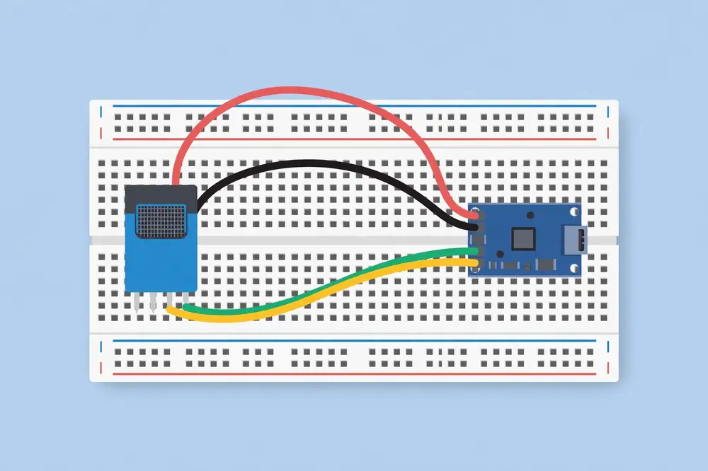
Wiring (voltage divider): an LDR (light-dependent resistor) changes resistance with light. Wire 3V3 → LDR → GPIO 34 → 10 kΩ resistor → GND. The junction between the LDR and the resistor goes to GPIO 34, so the pin sees a voltage that rises as light increases.
// Analog light sensor read on ADC1 (GPIO 34).

const int LDR_PIN = 34;

void setup() {
  Serial.begin(115200);
  delay(1000);
  analogReadResolution(12);          // explicit: 12-bit, 0..4095 (the default)
  Serial.println("LDR readings (0..4095):");
}

void loop() {
  int raw = analogRead(LDR_PIN);     // 0..4095
  float voltage = raw * (3.3 / 4095.0);
  Serial.print("raw=");
  Serial.print(raw);
  Serial.print("  voltage=");
  Serial.print(voltage, 2);
  Serial.println(" V");
  delay(500);
}
Expected Serial Monitor output (values move as you shade/uncover the LDR):
LDR readings (0..4095):
raw=2871  voltage=2.31 V
raw=2890  voltage=2.33 V
raw=412   voltage=0.33 V      <-- hand shading the sensor
raw=405   voltage=0.33 V
raw=2905  voltage=2.34 V      <-- hand removed
If the numbers barely move, your divider resistor value is mismatched to the LDR — try 4.7 kΩ or 22 kΩ and watch the swing grow.
The DHT22 (also sold as AM2302) measures temperature (−40 to +80 °C, ±0.5 °C) and humidity (0–100 %, ±2 %) — good enough for room monitoring, agriculture sheds, and most student research. The cheaper DHT11 is less accurate (±2 °C, ±5 %) and slower; the wiring and code are identical, only the DHTTYPE changes. Most DHT modules sold for breadboard use have 3 or 4 pins: VCC, DATA, GND (a fourth NC pin is unused).
Step 1 — Install the library. In the IDE: Sketch → Include Library → Manage Libraries, search "DHT sensor library" by Adafruit, and install it (it will offer the Adafruit Unified Sensor dependency — accept and install that too). Note the version numbers in your lab notes.
Step 2 — Wiring:
| DHT module pin | ESP32 pin |
|---|---|
| VCC (+) | 3V3 |
| DATA (out) | GPIO 15 |
| GND (−) | GND |
Many modules include the required pull-up resistor on the DATA line already. If you have a bare 4-pin sensor (no module board), add a 10 kΩ resistor between DATA and VCC yourself.
Step 3 — The sketch:
// DHT22 temperature & humidity reader (ESP32).
// Library: "DHT sensor library" by Adafruit (+ Adafruit Unified Sensor).
// Wiring: VCC->3V3, DATA->GPIO 15, GND->GND.

#include "DHT.h"

#define DHTPIN 15
#define DHTTYPE DHT22     // use DHT11 here if that is your sensor

DHT dht(DHTPIN, DHTTYPE);

void setup() {
  Serial.begin(115200);
  delay(1000);
  dht.begin();
  Serial.println("DHT22 reader started.");
}

void loop() {
  // The DHT22 needs ~2 seconds between reads. Respect it.
  delay(2000);

  float humidity = dht.readHumidity();
  float tempC = dht.readTemperature();        // Celsius; pass true for Fahrenheit

  // The library returns NaN ("not a number") when the read fails.
  if (isnan(humidity) || isnan(tempC)) {
    Serial.println("Failed to read from DHT sensor! Check wiring.");
    return;   // skip the rest of this loop pass and try again
  }

  float heatIndex = dht.computeHeatIndex(tempC, humidity, false);

  Serial.print("Humidity: ");
  Serial.print(humidity, 1);
  Serial.print(" %   Temperature: ");
  Serial.print(tempC, 1);
  Serial.print(" C   Heat index: ");
  Serial.print(heatIndex, 1);
  Serial.println(" C");
}
DHT22 reader started.
Humidity: 54.2 %   Temperature: 27.8 C   Heat index: 29.1 C
Humidity: 54.1 %   Temperature: 27.8 C   Heat index: 29.0 C
Humidity: 54.3 %   Temperature: 27.9 C   Heat index: 29.2 C
Breathe gently on the sensor: humidity should climb several percent within seconds and temperature nudge upward — a satisfying physical confirmation that the numbers are real.
Failed to read from DHT sensor! every time: wrong DHTTYPE (DHT11 vs DHT22), DATA wire on the wrong GPIO, missing pull-up on a bare sensor, or the sensor is wired to 5 V logic expectations — keep VCC at 3.3 V.delay(2000) is mandatory, not stylistic.For your research: Every sensor has an accuracy specification (±0.5 °C, ±2 % RH for the DHT22) and a sampling limit (one read per 2 s). Both belong in your paper's methodology: "temperature was sampled every 5 s with a DHT22 (±0.5 °C)". Reviewers check whether your claimed findings are even resolvable by your instruments — a 0.2 °C effect measured with a ±0.5 °C sensor is not a finding. Also log raw values alongside converted ones; raw logs let you re-calibrate after the fact.
Real analog signals jitter — electrical noise, not real change. The standard cure is averaging several quick reads. This helper takes 10 samples and returns the mean; use it anywhere stability matters:
int readAveraged(int pin, int samples = 10) {
  long total = 0;
  for (int i = 0; i < samples; i++) {
    total += analogRead(pin);
    delay(5);
  }
  return total / samples;
}
Call readAveraged(LDR_PIN) instead of analogRead(LDR_PIN). For slow signals (room temperature, soil moisture) a moving average over seconds is even better — but simple multi-sampling already removes most flicker. In research logging, note your averaging method in the methodology: "each reported value is the mean of 10 ADC samples" is a sentence reviewers expect.
A divider of two resistors scales a voltage down: with R1 from the sensor output to the pin and R2 from the pin to GND, Vpin = Vsensor × R2 / (R1 + R2). To map 0–5 V into 0–3.3 V, use R1 = 20 kΩ and R2 = 39 kΩ (ratio ≈ 0.66 → 5 V becomes 3.3 V). Verify with a multimeter before connecting. When in doubt, choose a 3.3 V-native sensor and skip the divider entirely.
| Sensor | Temperature accuracy | Humidity accuracy | Notes |
|---|---|---|---|
| DHT11 | ±2 °C | ±5 % RH | Cheapest; fine for demos, weak for research |
| DHT22 / AM2302 | ±0.5 °C | ±2 % RH | The sweet spot; used in this book |
| BME280 | ±0.5 °C | ±3 % RH | Adds barometric pressure + I2C interface; the research favorite |
The BME280 (I2C, Adafruit library available) is the natural upgrade when your paper needs pressure data or tighter specs. The wiring differs (SDA→GPIO 21, SCL→GPIO 22 on the default I2C bus), but the read-publish-sleep architecture stays identical.
The classic capacitive soil-moisture sensor (the corrosion-resistant kind, not the bare resistive probes that dissolve in weeks) outputs an analog voltage: wetter soil → lower voltage on most modules. It is the sensor behind every smart-agriculture demo, and it exercises everything in this chapter.
Wiring: VCC → 3V3, GND → GND, AOUT (analog out) → GPIO 34. Insert the probe into soil; do not submerge the electronics.
Calibration is the whole game. Raw values are meaningless until anchored: record the reading in completely dry soil (DRY_VALUE) and in a glass of water (WET_VALUE), then map:
// Soil moisture as a percentage, calibrated to your sensor and soil.

const int SOIL_PIN = 34;
const int DRY_VALUE = 3200;   // <-- replace with YOUR dry-soil reading
const int WET_VALUE = 1200;   // <-- replace with YOUR in-water reading

int readAveraged(int pin, int samples = 20) {
  long total = 0;
  for (int i = 0; i < samples; i++) { total += analogRead(pin); delay(5); }
  return total / samples;
}

void setup() {
  Serial.begin(115200);
  delay(1000);
  Serial.println("Soil moisture monitor. Calibrate DRY_VALUE/WET_VALUE first!");
}

void loop() {
  int raw = readAveraged(SOIL_PIN);
  // Constrain, then map dry->0% ... wet->100%.
  int moisture = map(constrain(raw, WET_VALUE, DRY_VALUE), DRY_VALUE, WET_VALUE, 0, 100);
  Serial.print("raw=");
  Serial.print(raw);
  Serial.print("  moisture=");
  Serial.print(moisture);
  Serial.println(" %");
  delay(2000);
}
Expected output (dip the probe in water mid-run):
raw=2890  moisture=16 %
raw=2844  moisture=18 %
raw=1310  moisture=96 %     <-- probe in water
raw=1295  moisture=97 %
Two research-grade lessons here: calibration is per-sensor and per-soil (your numbers will differ from anyone else's — publish your calibration procedure, not just the code), and capacitive probes drift as soil chemistry changes, so re-calibrate periodically and log the calibration constants with the data.
Faster is not better. Match the interval to the physics: room temperature changes over minutes (10–60 s sampling is plenty), soil moisture over hours (5–15 min), while vibration or sound need kilohertz rates the analogRead-in-loop() approach cannot sustain (that needs continuous ADC/DMA modes — advanced territory). Oversampling wastes power and storage and buys nothing; the right rate is the slowest one that still captures the phenomenon — a sentence that belongs in every methodology.
Key takeaways:
- ESP32 ADC is 12-bit (0–4095 for 0–3.3 V); never feed it more than ~3.3 V.
- Use ADC1 pins (commonly GPIO 32–39) for analog reads — ADC2 conflicts with Wi-Fi.
- The DHT22 gives calibrated digital temperature/humidity over one wire; respect its 2-second minimum interval and always check for NaN.
- Quote sensor accuracy and sampling rate in your methodology — your instruments bound your claims.
The ESP32's Wi-Fi can operate in station mode (joining an existing network, like your phone does — this is what you want), access-point mode (creating its own network others join), or both. Connection is handled by the built-in WiFi library: you give it the network name (SSID) and password, and it negotiates the rest (DHCP address, etc.) automatically.
One hard constraint to know upfront: the ESP32 connects to 2.4 GHz Wi-Fi only. It cannot see 5 GHz networks. If your router uses one merged network name for both bands, the ESP32 usually still connects (the router steers it to 2.4 GHz), but if connection mysteriously fails, check whether your SSID is 5 GHz-only or uses WPA3-only security — the ESP32 is happiest with WPA2 on 2.4 GHz.
Wiring: none — the antenna is on the module.
// ESP32 Wi-Fi station-mode connection with signal-strength reporting.
// Replace SSID and PASSWORD with your own. 2.4 GHz WPA2 network required.

#include <WiFi.h>

const char* SSID = "YOUR_WIFI_NAME";
const char* PASSWORD = "YOUR_WIFI_PASSWORD";

void setup() {
  Serial.begin(115200);
  delay(1000);

  Serial.print("Connecting to ");
  Serial.println(SSID);

  WiFi.mode(WIFI_STA);          // station mode: join an existing network
  WiFi.begin(SSID, PASSWORD);

  // Wait for connection, with a timeout so we never hang forever.
  int attempts = 0;
  while (WiFi.status() != WL_CONNECTED && attempts < 40) {
    delay(500);
    Serial.print(".");
    attempts++;
  }
  Serial.println();

  if (WiFi.status() == WL_CONNECTED) {
    Serial.println("Connected!");
    Serial.print("IP address: ");
    Serial.println(WiFi.localIP());
    Serial.print("Signal strength (RSSI): ");
    Serial.print(WiFi.RSSI());
    Serial.println(" dBm");
  } else {
    Serial.println("FAILED to connect. Check SSID/password and 2.4 GHz band.");
  }
}

void loop() {
  // Report signal strength every 10 seconds and watch for disconnects.
  if (WiFi.status() == WL_CONNECTED) {
    Serial.print("RSSI: ");
    Serial.print(WiFi.RSSI());
    Serial.println(" dBm");
  } else {
    Serial.println("Wi-Fi disconnected! Attempting reconnect...");
    WiFi.reconnect();
  }
  delay(10000);
}
RSSI (received signal strength indicator), measured in dBm, is negative — closer to zero is stronger:
| RSSI | Meaning |
|---|---|
| −30 to −50 dBm | Excellent (same room as router) |
| −50 to −65 dBm | Good (reliable for sensor nodes) |
| −65 to −75 dBm | Fair (works, but watch for drops) |
| Below −75 dBm | Weak (expect disconnects; move closer or add an access point) |
Walk around with the board powered from a USB power bank and watch the numbers change — you are doing a one-device site survey, exactly what Chapter 12's deployment step asks for.
Connecting to MyHomeWiFi
.........
Connected!
IP address: 192.168.1.42
Signal strength (RSSI): -58 dBm
RSSI: -58 dBm
RSSI: -61 dBm
RSSI: -59 dBm
The dots appear one per half-second while connecting; the IP address will match your own network's range.
WiFi.status() stuck at WL_NO_SSID_AVAIL: the SSID is not visible — check spelling, band, and that the network is not hidden (hidden SSIDs need extra configuration).For your research: Signal strength is data, not trivia. Papers on wireless sensor deployments routinely report RSSI distributions, packet-delivery ratios, and reconnect counts — they are the evidence that your deployment was real rather than a desk demo. Add a line to your logger that records RSSI with every sensor reading (Chapter 12 does this), and your methodology gains a wireless-characterization paragraph almost for free.
Before joining a network, it helps to see what the ESP32 sees. This scan sketch lists every visible access point with RSSI and security type — the fastest way to confirm "2.4 GHz vs 5 GHz" suspicions:
// Wi-Fi network scanner (ESP32).

#include <WiFi.h>

void setup() {
  Serial.begin(115200);
  delay(1000);
  WiFi.mode(WIFI_STA);
  WiFi.disconnect();   // ensure a clean scan
  delay(100);

  Serial.println("Scanning...");
  int n = WiFi.scanNetworks();
  Serial.print(n);
  Serial.println(" networks found:");
  for (int i = 0; i < n; i++) {
    Serial.print(i + 1);
    Serial.print(": ");
    Serial.print(WiFi.SSID(i));
    Serial.print("  (");
    Serial.print(WiFi.RSSI(i));
    Serial.print(" dBm)  ");
    Serial.println(WiFi.encryptionType(i) == WIFI_AUTH_OPEN ? "open" : "secured");
  }
}

void loop() {
  delay(10000);   // scan once; press EN to re-scan
}
Expected output:
Scanning...
6 networks found:
1: MyHomeWiFi  (-52 dBm)  secured
2: MyHomeWiFi_5G  (-58 dBm)  secured
3: NeighborNet  (-71 dBm)  secured
...
If your network appears only with a _5G suffix (or not at all while your phone sees it), you have confirmed a band problem — enable the 2.4 GHz radio on your router or use a hotspot.
Sometimes there is no router — a field site, a demo table. The ESP32 can be the network:
#include <WiFi.h>
const char* AP_SSID = "ESP32-Field-Node";
const char* AP_PASS = "field1234";

void setup() {
  Serial.begin(115200);
  WiFi.mode(WIFI_AP);
  WiFi.softAP(AP_SSID, AP_PASS);
  Serial.print("AP IP address: ");
  Serial.println(WiFi.softAPIP());   // typically 192.168.4.1
}
void loop() {}
Your phone joins ESP32-Field-Node and can reach the board at 192.168.4.1. Combined with a tiny web page served by the ESP32 (an ESPAsyncWebServer project for later), this becomes a configuration portal — the professional answer to "hardcoded credentials" from Chapter 6's troubleshooting.
DHCP addresses change when the router reboots, which breaks bookmarks and firewall rules. For fixed installations, either reserve the address in the router (best — no code change) or call WiFi.config(staticIP, gateway, subnet) before WiFi.begin(). Either way, record the address in your deployment notes; "the node" is not an address.
One RSSI reading is a snapshot; a log is evidence. This sketch appends timestamped readings you can paste into a spreadsheet — the technique behind every wireless characterization in published sensor work:
// RSSI logger: CSV output for spreadsheet analysis.

#include <WiFi.h>
const char* SSID = "YOUR_WIFI_NAME";
const char* PASSWORD = "YOUR_WIFI_PASSWORD";

void setup() {
  Serial.begin(115200);
  WiFi.mode(WIFI_STA);
  WiFi.begin(SSID, PASSWORD);
  while (WiFi.status() != WL_CONNECTED) { delay(500); Serial.print("."); }
  Serial.println("\nseconds,rssi_dbm");
}

void loop() {
  static unsigned long start = millis();
  if (WiFi.status() == WL_CONNECTED) {
    Serial.print((millis() - start) / 1000);
    Serial.print(",");
    Serial.println(WiFi.RSSI());
  } else {
    Serial.println("disconnected, reconnecting...");
    WiFi.reconnect();
    delay(2000);
  }
  delay(5000);
}
Expected output:
seconds,rssi_dbm
0,-58
5,-60
10,-59
15,-63
20,-58
Copy 10 minutes of this into a spreadsheet, compute min/max/mean/standard deviation, and you have a link-quality characterization — exactly the table reviewers expect in a deployment section.
Three philosophies, in order of robustness: (1) Block until connected (Chapter 6's first sketch) — simplest, but a dead router wedges the node forever. Fine for bench work. (2) Retry with timeout, then continue degraded — the capstone's approach: attempt, and if it fails, sleep and try next cycle. Right for battery nodes. (3) Background auto-reconnect — WiFi.setAutoReconnect(true) plus event callbacks (WiFi.onEvent) that fire on disconnect/connect, letting the main loop keep sensing while Wi-Fi heals itself. Most robust for mains-powered gateways; slightly more code. Choose by asking: "what should this node do if the network never comes back?" — then implement that answer.
University and corporate Wi-Fi often uses WPA2-Enterprise (username + password, no pre-shared key) or captive portals (click-through login pages). The ESP32's Arduino WiFi library supports enterprise auth via WiFi.begin(ssid, WPA2_AUTH_PEAP, username, password)-style calls, but captive portals are effectively impossible for a headless microcontroller. For campus deployments, request an IoT/PSK SSID from IT, or use a dedicated hotspot — document whichever you chose, because it constrains where your results generalize.
DHCP addresses change, which is annoying when you want to reach a node. Three answers:
WiFi.localIP() printed at boot — simple, requires USB.esp32-node.local on the local network. Add #include <ESPmDNS.h> and MDNS.begin("esp32-node") after Wi-Fi connects; then ping esp32-node.local from your computer. (Windows needs Bonjour/iTunes installed for .local names; macOS and Linux handle them natively.)How much data can a node actually move? A JSON reading of ~100 bytes every 10 s is 600 bytes/minute — trivial. Even at one reading per second, you are far below Wi-Fi's capacity; the constraints are power (each transmit burst costs battery) and broker/endpoint politeness (public services throttle aggressive clients), not bandwidth. Design around energy and etiquette: batch readings and transmit in bursts if you need history, keep payloads small, and remember that for environmental sensing, the physics changes slowly — the network is never the bottleneck.
Between full-active and deep sleep lies a useful middle ground: modem sleep, where the CPU keeps running but the radio duty-cycles between access-point beacons. The Arduino core enables a light form of this automatically when Wi-Fi idles, but you can tune it: WiFi.setSleep(true) allows modem sleep (default on most cores), while WiFi.setSleep(false) forces the radio always-on for minimum latency — useful when a node must react to subscribed MQTT commands instantly. The tradeoff is concrete: always-on Wi-Fi draws ~100+ mA continuously; modem sleep cuts that roughly fivefold at the cost of ~10–100 ms extra latency on incoming packets. For mains-powered actuators (a relay board awaiting commands), disable sleep; for battery nodes that only transmit, leave it on and let deep sleep handle the rest.
The ESP32's headline feature — Wi-Fi and Bluetooth on one chip — comes with a hardware footnote: both radios share the same 2.4 GHz antenna and front-end. They time-slice rather than truly operating simultaneously, which has two practical consequences: running BLE (Bluetooth Low Energy) alongside Wi-Fi slightly reduces Wi-Fi throughput and increases power draw, and classic Bluetooth's frequency hopping can add jitter to latency-sensitive Wi-Fi traffic. For this book's sensor nodes (Wi-Fi only) it is irrelevant — but when you later add BLE provisioning or beaconing, test the combination under load rather than assuming independence. Espressif's documentation describes coexistence configuration options for advanced use; the default settings are correct for beginners.
Key takeaways:
- Use station mode (WIFI_STA); the ESP32 needs a 2.4 GHz WPA2 network — it cannot join 5 GHz.
- Always bound your connection wait with a timeout; never while(true) on Wi-Fi.
- RSSI in dBm tells you link quality: above −65 is comfortable, below −75 is trouble.
- WiFi.reconnect() in the loop plus RSSI logging turns a fragile demo into a deployable node.
Your sensor node needs to get readings to somewhere useful — a dashboard, a database, a phone alert. You could have the node push data directly to each consumer, but that tangles every device with every destination. MQTT solves this with the publish/subscribe pattern: devices publish messages to named channels called topics on a central broker, and any number of subscribers receive them. Publishers and subscribers never talk to each other directly; they only talk to the broker.
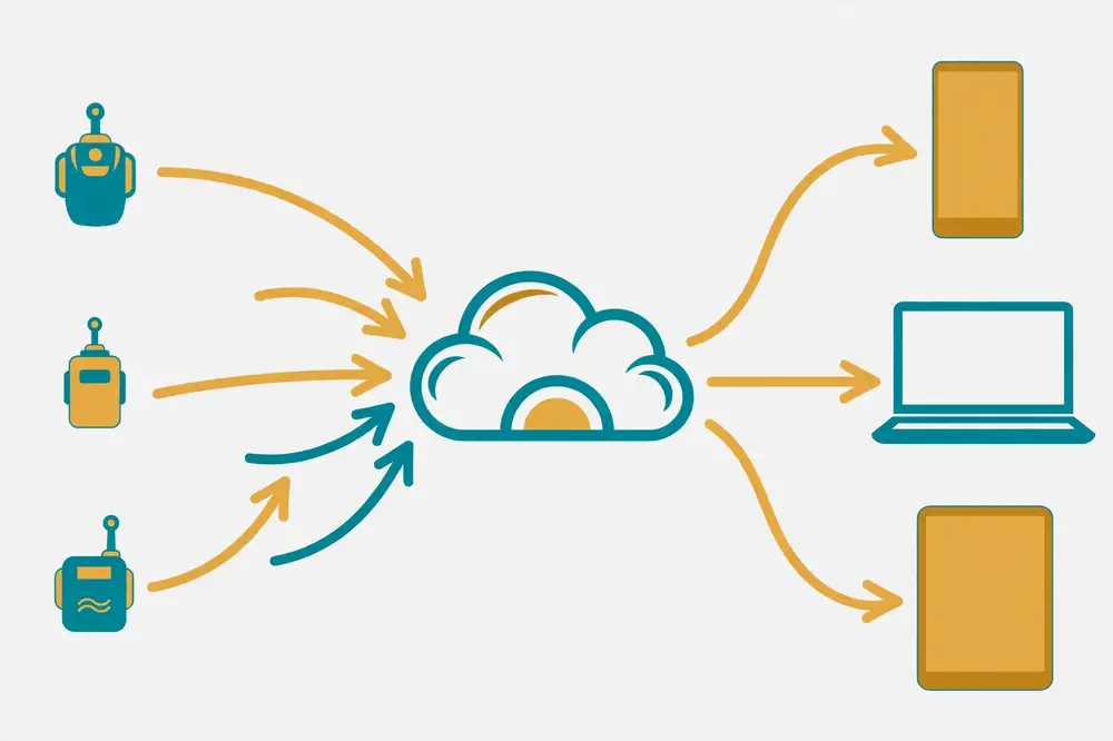
MQTT was designed for exactly this job — tiny devices, unreliable networks, minimal bandwidth. Messages are small, the protocol keeps a persistent connection with lightweight keep-alive pings, and three Quality of Service levels let you choose between "fire and forget" (QoS 0), "deliver at least once" (QoS 1), and "deliver exactly once" (QoS 2). For sensor telemetry, QoS 0 or 1 is the norm. MQTT is an open OASIS standard, and the public documentation at mqtt.org describes the protocol in full.
A topic looks like a path: home/livingroom/temperature. Subscribers use wildcards: home/+/temperature (the + matches one level) or home/# (the # matches everything below). Designing a clean topic hierarchy up front — site/room/measurement — saves painful refactoring later.
For learning, use a public test broker. test.mosquitto.org (run by the Eclipse Mosquitto project) is the long-standing public test instance: no account needed, reachable at port 1883. Never publish private or sensitive data to a public broker — anyone can subscribe to your topics. For real deployments you run your own broker (Mosquitto on a Raspberry Pi or VPS takes minutes) or use a managed one.
The standard Arduino MQTT library is PubSubClient by Nick O'Leary. Its usage pattern has four parts you will reuse in every MQTT project:
WiFiClient and a PubSubClient pointing at the broker.client.loop() often — this pumps the keep-alive and delivers incoming messages. Starve it (with long delay()s) and the broker disconnects you.This chapter publishes the DHT22 readings from Chapter 5, so keep that wiring: VCC→3V3, DATA→GPIO 15, GND→GND.
Sketch → Include Library → Manage Libraries, search "PubSubClient" by Nick O'Leary, install. (You need the DHT library from Chapter 5 as well.)
// ESP32 MQTT sensor publisher (PubSubClient pattern).
// Publishes DHT22 temperature/humidity to test.mosquitto.org every 10 s.
// Libraries: PubSubClient (Nick O'Leary), DHT sensor library (Adafruit).

#include <WiFi.h>
#include <PubSubClient.h>
#include "DHT.h"

// ---- configure these ----
const char* SSID = "YOUR_WIFI_NAME";
const char* PASSWORD = "YOUR_WIFI_PASSWORD";
const char* MQTT_BROKER = "test.mosquitto.org";
const int   MQTT_PORT = 1883;
const char* TOPIC_TEMP = "astolixgen/demo/lab1/temperature";
const char* TOPIC_HUM  = "astolixgen/demo/lab1/humidity";
// Use YOUR OWN unique topic prefix (not "astolixgen/demo") on public brokers.

#define DHTPIN 15
#define DHTTYPE DHT22
DHT dht(DHTPIN, DHTTYPE);

WiFiClient espClient;
PubSubClient client(espClient);
unsigned long lastPublish = 0;
const unsigned long PUBLISH_INTERVAL = 10000;  // 10 seconds

void connectWiFi() {
  WiFi.mode(WIFI_STA);
  WiFi.begin(SSID, PASSWORD);
  Serial.print("Connecting to Wi-Fi");
  int attempts = 0;
  while (WiFi.status() != WL_CONNECTED && attempts < 40) {
    delay(500); Serial.print("."); attempts++;
  }
  Serial.println(WiFi.status() == WL_CONNECTED ? " OK" : " FAILED");
}

void connectMQTT() {
  // Loop until reconnected. A unique client ID avoids broker conflicts.
  while (!client.connected()) {
    Serial.print("Connecting to MQTT broker...");
    String clientId = "esp32-" + String((uint32_t)ESP.getEfuseMac(), HEX);
    if (client.connect(clientId.c_str())) {
      Serial.println("connected.");
    } else {
      Serial.print("failed, rc=");
      Serial.print(client.state());
      Serial.println(" - retrying in 5 s");
      delay(5000);
    }
  }
}

void setup() {
  Serial.begin(115200);
  delay(1000);
  dht.begin();
  connectWiFi();
  client.setServer(MQTT_BROKER, MQTT_PORT);
}

void loop() {
  if (WiFi.status() != WL_CONNECTED) { connectWiFi(); }
  if (!client.connected()) { connectMQTT(); }
  client.loop();   // keep-alive + incoming messages: call as often as possible

  if (millis() - lastPublish >= PUBLISH_INTERVAL) {
    lastPublish = millis();

    float h = dht.readHumidity();
    float t = dht.readTemperature();
    if (isnan(h) || isnan(t)) {
      Serial.println("DHT read failed, skipping publish.");
      return;
    }

    char payload[16];
    snprintf(payload, sizeof(payload), "%.1f", t);
    client.publish(TOPIC_TEMP, payload);
    snprintf(payload, sizeof(payload), "%.1f", h);
    client.publish(TOPIC_HUM, payload);

    Serial.print("Published: temp=");
    Serial.print(t, 1);
    Serial.print(" C, hum=");
    Serial.print(h, 1);
    Serial.println(" %");
  }
}
Study the architecture: loop() does three jobs every pass — heal the connections, pump the MQTT client, and publish on a timer. The publishing uses millis() timing (Chapter 4's pattern) so client.loop() never starves. The client ID is derived from the chip's unique MAC address so two of your boards never clash on the broker.
Connecting to Wi-Fi......... OK
Connecting to MQTT broker...connected.
Published: temp=27.8 C, hum=54.2 %
Published: temp=27.9 C, hum=54.1 %
Published: temp=27.9 C, hum=54.3 %
To prove the data really leaves the building, subscribe from your computer. If you have Python, pip install paho-mqtt and run a tiny subscriber on topic astolixgen/demo/lab1/# — or use any free MQTT dashboard app on your phone pointed at test.mosquitto.org:1883 with the same topic. Seeing your phone update every 10 seconds with live readings from the little board on your desk is the moment MQTT "clicks."
failed, rc=-2 looping: the broker is unreachable — no internet route, DNS blocked, or the public broker is down (it happens). Test from your phone's MQTT app on the same network to isolate board vs. broker.client.loop() is starved by a long delay() somewhere — the keep-alive never goes out. Keep delays short or restructure with millis().For your research: MQTT topic design is research-infrastructure design. A scheme like
campus/building-A/room-204/temperaturelets you add fifty nodes without touching subscriber code, and logging every message with a broker-side timestamp gives you a complete, replayable dataset. In a paper, one sentence — "readings were published via MQTT (QoS 1) to topicgreenhouse/zone-2/...at 10 s intervals and archived by a subscriber" — tells reviewers your data pipeline is real and reproducible. Keep a sample of raw MQTT payloads in your appendix or repository; it is the closest thing to primary evidence.
Publishing is only half of MQTT. Subscribing lets the node receive commands — the foundation of actuators (relays, pumps, alarms). The pattern: register a callback function, subscribe after connecting, and let client.loop() deliver messages into the callback:
// Add to the Chapter 7 sketch: subscribe to a command topic.

const char* TOPIC_CMD = "astolixgen/demo/lab1/led";  // YOUR OWN prefix
const int LED_PIN = 2;

void mqttCallback(char* topic, byte* payload, unsigned int length) {
  String msg;
  for (unsigned int i = 0; i < length; i++) msg += (char)payload[i];
  msg.trim();
  Serial.print("Command received: ");
  Serial.println(msg);
  if (msg == "on")       digitalWrite(LED_PIN, HIGH);
  else if (msg == "off") digitalWrite(LED_PIN, LOW);
}

// in setup(), after WiFi connects:
 // client.setCallback(mqttCallback);
// in connectMQTT(), after client.connect() succeeds:
 // client.subscribe(TOPIC_CMD);
Keep callbacks short — set flags or outputs directly, never delay() inside. Publish the command from your phone's MQTT app (on/off) and watch the board's LED obey: you have built bidirectional IoT, the basis of every "smart" device.
Two broker features worth knowing:
.../status = "offline"); if the node disconnects unexpectedly, the broker publishes it automatically. Subscribers then distinguish "node asleep" from "node dead" — set the will in client.connect() via its overloads, and publish "online" (retained) on each successful boot. Fleet-health dashboards are built on exactly this.QoS 0 (at most once) is fine for 10-second temperature telemetry — losing one reading in a thousand is invisible. Use QoS 1 (at least once) for commands and alarms where a lost message matters; accept the small overhead of acknowledgments. QoS 2 (exactly once) is rarely needed on Arduino-class devices and PubSubClient's default configuration focuses on QoS 0/1 — another reason to keep telemetry idempotent (each message self-contained, so duplicates or gaps never corrupt the dataset).
One node tolerates sloppy topics; twenty nodes punish them. Design rules that scale:
campus/building-a/floor-2/room-204/temperature. Every level you add is a future filter you get for free..../temperature (data), .../status (online/offline via LWT), .../cmd/led (commands in). Mixing them forces every subscriber to parse message types.With wildcards, one subscriber to campus/# archives everything, while campus/building-a/+/room-204/# isolates a single room across floors. Good hierarchy turns "add a node" into a zero-code operation.
test.mosquitto.org) — for learning only. No privacy, no uptime guarantees, no authentication.Whichever you choose, the ESP32 code barely changes — only the broker address, port, and credentials. That portability is the payoff of learning the standard pattern rather than a vendor's SDK.
Chapter 7 publishes bare values (27.8) — simplest, and fine for one measurement per topic. The capstone publishes JSON documents — better when a message carries several fields plus metadata (node, firmware, RSSI). Rule: one value per topic → plain text; anything richer → JSON. And whatever you choose, freeze the schema early: changing payload formats mid-deployment corrupts datasets silently, while versioned schemas ("v":1 field) let parsers evolve safely.
Key takeaways:
- MQTT = publish/subscribe via a broker; topics are hierarchical paths, wildcards (+, #) select subtrees.
- The PubSubClient pattern: configure → connect/reconnect → publish on a millis() timer → call client.loop() constantly.
- Use a unique client ID (MAC-based) and your own topic prefix on public brokers; never send private data to one.
- A phone MQTT app subscribing to your topic is the fastest end-to-end verification.
MQTT is ideal for continuous telemetry, but much of the internet speaks HTTP — the request/response protocol behind every web page and REST API. An ESP32 can act as an HTTP client: it opens a connection to a server, sends a request (GET to fetch, POST to submit data), and reads the response with its status code (200 OK, 404 Not Found, 500 Server Error) and body.
For a sensor node, the typical use is POSTing a JSON payload to a data-collection endpoint: {"temperature": 27.8, "humidity": 54.2, "rssi": -61}. Your own server, a cloud function, or a service like ThingSpeak/MQTT-to-cloud bridges all accept this shape.
To learn HTTP without standing up a server, use httpbin.org — a free, long-running request-inspection service. POST anything to http://httpbin.org/post and it echoes back exactly what you sent, with headers and metadata. It is the standard scratch endpoint for HTTP client development. (Use plain http:// here — the ESP32 can do HTTPS too, but certificate handling adds complexity covered in the dashboard's "next steps.")
Arduino-ESP32's HTTPClient library (built into the core — no install needed) follows a tidy pattern: begin(url) → addHeader(...) → POST(payload) → read httpResponseCode and body → end() to free the connection. Forgetting end() leaks the connection and eventually exhausts memory — the embedded equivalent of leaving files open.
Same DHT22 wiring as Chapters 5 and 7 (VCC→3V3, DATA→GPIO 15, GND→GND). No new hardware.
// ESP32 HTTP POST: send DHT22 readings as JSON to a test endpoint.
// Endpoint: http://httpbin.org/post  (echoes your data back for verification)
// No extra library needed: HTTPClient ships with the ESP32 Arduino core.

#include <WiFi.h>
#include <HTTPClient.h>
#include "DHT.h"

const char* SSID = "YOUR_WIFI_NAME";
const char* PASSWORD = "YOUR_WIFI_PASSWORD";
const char* POST_URL = "http://httpbin.org/post";

#define DHTPIN 15
#define DHTTYPE DHT22
DHT dht(DHTPIN, DHTTYPE);

unsigned long lastPost = 0;
const unsigned long POST_INTERVAL = 30000;  // 30 seconds (be polite to free services)

void setup() {
  Serial.begin(115200);
  delay(1000);
  dht.begin();

  WiFi.mode(WIFI_STA);
  WiFi.begin(SSID, PASSWORD);
  Serial.print("Connecting to Wi-Fi");
  while (WiFi.status() != WL_CONNECTED) { delay(500); Serial.print("."); }
  Serial.println("\nWi-Fi connected.");
}

void loop() {
  if (millis() - lastPost >= POST_INTERVAL) {
    lastPost = millis();

    float h = dht.readHumidity();
    float t = dht.readTemperature();
    if (isnan(h) || isnan(t)) {
      Serial.println("DHT read failed, skipping POST.");
      return;
    }

    // Build the JSON payload by hand (small and dependency-free).
    char payload[128];
    snprintf(payload, sizeof(payload),
             "{\"temperature\":%.1f,\"humidity\":%.1f,\"rssi\":%d}",
             t, h, WiFi.RSSI());

    HTTPClient http;
    http.begin(POST_URL);
    http.addHeader("Content-Type", "application/json");

    int code = http.POST((uint8_t*)payload, strlen(payload));
    Serial.print("POST -> HTTP ");
    Serial.println(code);

    if (code == 200) {
      String body = http.getString();
      // The echo is long; print just the first 300 characters.
      Serial.println(body.substring(0, 300));
    } else {
      Serial.println("POST failed. Check network/DNS.");
    }
    http.end();   // always release the connection
  }
  delay(100);  // small idle; nothing else to do in this sketch
}
Hand-building JSON with snprintf is fine for three fields and avoids adding a JSON library. If your payload grows (nested objects, arrays), switch to the ArduinoJson library — it is the community standard and is listed in the dashboard checklist.
Connecting to Wi-Fi.....
Wi-Fi connected.
POST -> HTTP 200
{
  "args": {},
  "data": "{\"temperature\":27.8,\"humidity\":54.2,\"rssi\":-61}",
  "files": {},
  "form": {},
  "headers": {
    "Content-Type": "application/json",
    ...
The echo proves your JSON arrived intact — the server received exactly the string you sent. In a real deployment, your own endpoint would parse this JSON and store the three fields in a database.
| Code | Meaning | What to do |
|---|---|---|
| 200 | OK | Success — your data arrived. |
| 400 | Bad Request | Your payload/format is wrong — print and inspect it. |
| 401/403 | Unauthorized/Forbidden | Missing or wrong API key — add the auth header. |
| 404 | Not Found | Wrong URL path — check the endpoint. |
| 429 | Too Many Requests | You are posting too fast — slow down (rate limit). |
| 500 | Server Error | Their problem, not yours — retry with backoff. |
| −1 (ESP32) | Connection failed | No route/DNS — check Wi-Fi and the hostname. |
payload string before sending; 90 % of API bugs are malformed JSON (missing quote, stray comma).http.end() in an earlier version of your code, or String fragmentation — the sketch above ends the client every cycle.http:// test endpoints; production HTTPS needs the root CA certificate loaded (dashboard "next steps").For your research: HTTP POST with JSON is the lingua franca between field hardware and research data infrastructure. When your paper says "sensor nodes POSTed JSON readings every 30 s to a REST endpoint backed by a time-series database," every reviewer understands the pipeline instantly — no custom protocol to explain or defend. Log the HTTP status code alongside each reading; a column of
200s is quantitative evidence of uplink reliability, and the failure codes document exactly when and how the link degraded.
POST sends data up; GET fetches data down — configuration, commands, or reference information. The pattern is nearly identical:
// HTTP GET example: fetch echoed request info from httpbin.

#include <WiFi.h>
#include <HTTPClient.h>

const char* SSID = "YOUR_WIFI_NAME";
const char* PASSWORD = "YOUR_WIFI_PASSWORD";

void setup() {
  Serial.begin(115200);
  WiFi.mode(WIFI_STA);
  WiFi.begin(SSID, PASSWORD);
  while (WiFi.status() != WL_CONNECTED) { delay(500); Serial.print("."); }
  Serial.println("\nConnected.");

  HTTPClient http;
  http.begin("http://httpbin.org/get?node=node1");
  int code = http.GET();
  Serial.print("GET -> HTTP ");
  Serial.println(code);
  if (code == 200) {
    Serial.println(http.getString().substring(0, 400));
  }
  http.end();
}

void loop() {}
Expected output (truncated): GET -> HTTP 200 followed by JSON showing your query parameters echoed back. Practical uses: a node fetching its sampling interval from a server at boot (remote configuration without reflashing), or pulling a weather forecast to decide whether to water plants.
When responses grow beyond a glance, parse them properly. Install ArduinoJson by Benoît Blanchon (Library Manager) — the community standard:
#include <ArduinoJson.h>

// ... after a successful GET with body in `String body`:
StaticJsonDocument<1024> doc;
DeserializationError err = deserializeJson(doc, body);
if (!err) {
  const char* origin = doc["origin"];      // httpbin returns caller IP here
  Serial.print("Server saw us as: ");
  Serial.println(origin);
}
Rule: size the document generously (StaticJsonDocument<2048> for small payloads), always check the deserialization error, and never parse untrusted JSON into fixed buffers without bounds — the library handles this if you let it.
Real cloud endpoints use https://. The ESP32 supports it, but certificate validation requires loading the server's root CA certificate (http.begin(url, rootCACertificate) or setInsecure() for testing only — never ship setInsecure()). TLS handshakes also cost RAM and seconds of awake time, which matters for Chapter 9's power budget. Learn on http:// test endpoints; add TLS when you move to your own infrastructure, and measure the extra awake time.
Posting JSON to httpbin proves your client works, but research needs the data stored and visible. The full pipeline has four stages, and you now understand the first two:
A minimal Flask receiver for testing looks like this (run on your computer, point the ESP32 at http://YOUR_PC_IP:5000/data):
from flask import Flask, request
app = Flask(__name__)

@app.route('/data', methods=['POST'])
def data():
    reading = request.get_json(force=True)
    print(reading)  # later: write to a database
    return {"status": "ok"}, 200

app.run(host='0.0.0.0', port=5000)
Your ESP32 POSTs to it exactly as it POSTed to httpbin — same code, different URL — and your terminal prints each reading. That is a complete private data pipeline with no cloud account required.
Free endpoints and shared networks have limits: posting every second to a free service will get you throttled (HTTP 429) or banned. Rules of thumb: 30–60 s intervals for environmental data (nothing physical changes faster), exponential backoff on failures (wait 5 s, then 10 s, then 20 s…), and never retry a 4xx error in a tight loop — 4xx means your request is wrong, and hammering it helps nobody. The capstone's bounded retries embody this.
The Chapter 8 sketch tries once per interval. Real firmware retries intelligently — immediate retries hammer struggling servers, so wait progressively longer (exponential backoff):
// POST with exponential backoff: 5 s, 10 s, 20 s, then give up until next cycle.

bool postWithRetry(const char* url, const char* payload) {
  HTTPClient http;
  http.begin(url);
  http.addHeader("Content-Type", "application/json");

  unsigned long waitMs = 5000;
  for (int attempt = 1; attempt <= 3; attempt++) {
    int code = http.POST((uint8_t*)payload, strlen(payload));
    Serial.print("Attempt ");
    Serial.print(attempt);
    Serial.print(" -> HTTP ");
    Serial.println(code);
    if (code == 200) { http.end(); return true; }
    if (code >= 400 && code < 500 && code != 429) {
      Serial.println("Client error: retrying won't help. Check the request.");
      break;   // your request is wrong; don't hammer the server
    }
    delay(waitMs);
    waitMs *= 2;
  }
  http.end();
  return false;
}
Notice the 4xx rule encoded: retry network failures and rate limits, but stop immediately on your mistakes. Call this from loop() in place of the inline POST, count successes, and you have the uplink-reliability metric Exercise 8 asks for.
They overlap, so choose deliberately:
The deciding question is not "which is better" but "who consumes the data, and what shape do they expect?" — answer that, and the protocol picks itself.
Key takeaways:
- ESP32 speaks HTTP via the built-in HTTPClient: begin → headers → POST → check code → end().
- httpbin.org/post echoes your payload — the perfect no-server way to verify your client.
- Always http.end(); always check the status code; include RSSI and timestamps in your JSON.
- Hand-rolled snprintf JSON is fine for tiny payloads; adopt ArduinoJson when structure grows.
Everything so far assumed USB power — infinite energy. Real research deployments do not have that luxury: a greenhouse node, a river-level monitor, or a classroom air-quality logger often runs on batteries or a small solar panel, far from any outlet. The ESP32's answer is deep sleep: the main processors, Wi-Fi, and Bluetooth shut down almost entirely, leaving only a tiny ultra-low-power coprocessor and a timer running. Current drops from ~100+ mA (Wi-Fi active) to roughly 10 µA — a ten-thousand-fold reduction.
The trade: in deep sleep the ESP32 forgets everything — RAM is cleared, Wi-Fi disconnects, and your program restarts from setup() on every wake. Design your firmware around that: wake → connect → read sensor → transmit → sleep again. A node that wakes for 10 seconds every 10 minutes is awake ~1.6 % of the time, so a battery that lasts a day of continuous operation can last for weeks.
The ESP32 can wake from several triggers; the two you need first are:
This chapter implements timer wake-up; the dashboard notes where to find EXT0 examples.
#include "esp_sleep.h"   // deep-sleep API (part of the ESP32 core)

#define uS_TO_S_FACTOR 1000000ULL   // microseconds -> seconds
#define TIME_TO_SLEEP  600          // sleep 600 s = 10 minutes

void setup() {
  Serial.begin(115200);
  delay(1000);

  // 1. Find out WHY we woke up.
  esp_sleep_wakeup_cause_t cause = esp_sleep_get_wakeup_cause();
  switch (cause) {
    case ESP_SLEEP_WAKEUP_TIMER:
      Serial.println("Woke from timer.");
      break;
    case ESP_SLEEP_WAKEUP_UNDEFINED:
    default:
      Serial.println("Fresh power-on (not a timer wake).");
      break;
  }

  // 2. Do the work: read sensor, connect Wi-Fi, publish. (Abbreviated here;
  //    in the capstone this is the full DHT + MQTT sequence.)
  Serial.println("Taking a reading...");
  float fakeTemp = 25.0 + random(-50, 50) / 10.0;
  Serial.print("Temperature: ");
  Serial.print(fakeTemp, 1);
  Serial.println(" C (placeholder - real sensor in Chapter 12)");
  Serial.println("Pretending to transmit... done.");

  // 3. Arm the timer and sleep.
  Serial.print("Sleeping for ");
  Serial.print(TIME_TO_SLEEP);
  Serial.println(" seconds. Goodnight.");
  Serial.flush();   // let the serial text finish before we vanish
  esp_sleep_enable_timer_wakeup(TIME_TO_SLEEP * uS_TO_S_FACTOR);
  esp_deep_sleep_start();

  // We never reach here. On wake, the chip reboots into setup().
}

void loop() {
  // Empty: everything happens in setup() because each wake is a fresh boot.
}
For a first test, change TIME_TO_SLEEP to 10 seconds so you can watch several cycles quickly.
Fresh power-on (not a timer wake).
Taking a reading...
Temperature: 24.3 C (placeholder - real sensor in Chapter 12)
Pretending to transmit... done.
Sleeping for 10 seconds. Goodnight.
Woke from timer.
Taking a reading...
Temperature: 25.1 C (placeholder - real sensor in Chapter 12)
Pretending to transmit... done.
Sleeping for 10 seconds. Goodnight.
Woke from timer.
...
Notice the first line differs on power-on vs. wake — that switch on the wake cause is how production firmware distinguishes "first boot, do one-time setup" from "routine wake, just sense and sleep."
Estimate battery life with the duty cycle:
average current = (awake_current × awake_time + sleep_current × sleep_time) / total_time
Example: awake 10 s at 120 mA (Wi-Fi transmitting), asleep 590 s at 0.01 mA:
(120 × 10 + 0.01 × 590) / 600 ≈ 2.0 mA average
A 2000 mAh battery ÷ 2.0 mA ≈ 1000 hours ≈ 41 days. Lengthen the sleep to 30 minutes and you pass 4 months. This one calculation belongs in every battery-powered paper's methodology — reviewers love it because it shows the deployment lifetime was engineered, not hoped for.
Practical notes: cheap devkit boards include a USB-serial chip and voltage regulator that draw milliamps even in deep sleep, limiting real-world savings — for maximum battery life, purpose-built low-power boards (or powering the module directly at 3.3 V with peripherals disconnected) do better. Always measure your actual sleep current with a USB meter or multimeter rather than trusting datasheet numbers alone.
esp_deep_sleep_start(), or you called sleep inside loop() after already sleeping — keep the canonical order: arm → start, at the end of setup().Serial.flush() before sleeping — the UART buffer is discarded on sleep entry.RTC_DATA_ATTR attribute) or write to flash/NVS sparingly (flash wears out after ~10,000–100,000 writes; RTC memory is the right tool for counters).For your research: Duty cycling is a first-class research topic, not just a trick: papers compare adaptive sampling (sleep longer when readings are stable, wake faster when they change) against fixed schedules, quantifying the energy-vs-freshness tradeoff. Even a simple version — "nodes slept 10 min, waking immediately if temperature changed >1 °C since last reading" — is a publishable engineering contribution in an applied IoT paper. And always report measured sleep current, not the datasheet's: measured numbers are evidence, datasheet numbers are hopes.
Deep sleep wipes RAM — but a small region of RTC memory survives. Mark a variable with RTC_DATA_ATTR and it persists across timer wakes (though not across full power loss):
// Counter that survives deep sleep.

#include "esp_sleep.h"
#define uS_TO_S_FACTOR 1000000ULL

RTC_DATA_ATTR int wakeCount = 0;   // preserved across deep sleep

void setup() {
  Serial.begin(115200);
  delay(500);
  wakeCount++;
  Serial.print("Wake number ");
  Serial.println(wakeCount);
  Serial.println("Sleeping 10 s...");
  Serial.flush();
  esp_sleep_enable_timer_wakeup(10 * uS_TO_S_FACTOR);
  esp_deep_sleep_start();
}
void loop() {}
Expected output: Wake number 1, then 2, 3… across sleeps. Unplug the USB and the count restarts at 1 — RTC memory survives sleep, not power loss. The capstone uses this for its boot counter; combined with MQTT, gaps in the sequence reveal lost cycles.
Timer wake-up suits periodic sensing. For event-driven nodes — a door sensor, a rain gauge tip, a PIR motion trigger — EXT0 wakes the chip when a single RTC-capable pin changes level:
// Wake when a button (GPIO 15 to GND) is pressed.

#include "esp_sleep.h"
#define BUTTON_PIN 15

void setup() {
  Serial.begin(115200);
  delay(500);
  esp_sleep_wakeup_cause_t cause = esp_sleep_get_wakeup_cause();
  if (cause == ESP_SLEEP_WAKEUP_EXT0) {
    Serial.println("Woke because the button was pressed!");
  } else {
    Serial.println("Power-on. Press the button to wake me next time.");
  }
  Serial.println("Sleeping until button press...");
  Serial.flush();
  esp_sleep_enable_ext0_wakeup((gpio_num_t)BUTTON_PIN, 0);  // wake when pin goes LOW
  esp_deep_sleep_start();
}
void loop() {}
Wire the button exactly as in Chapter 4 (GPIO 15 to GND, internal pull-up enabled by the sleep hardware). The board now draws microamps indefinitely until someone presses the button — the architecture behind battery door/window sensors that last a year.
Datasheet sleep figures assume an ideal board. Measure yours: put a USB current meter (a few dollars) between the supply and the board, or insert a multimeter in series on the 5 V line. Record three numbers — active-with-Wi-Fi, active-idle, and deep-sleep — and use the measured values in your duty-cycle math. If deep sleep reads milliamps on a devkit, that is the USB-serial chip and regulator, not your code; note it, and know that a purpose-built board would do better.
Deep sleep is the deepest, but the ESP32 offers a ladder — pick the shallowest rung that meets your goal:
| Mode | What stays on | Typical current | Wake behavior |
|---|---|---|---|
| Active (Wi-Fi on) | Everything | 100–200 mA | — |
| Modem sleep | CPU on, Wi-Fi radio cycled | ~20 mA | Instant, automatic |
| Light sleep | CPU paused, RAM kept | ~1 mA | Fast resume, program continues |
| Deep sleep | Only RTC + timer | ~10 µA | Reboot into setup() |
Modem sleep happens automatically between Wi-Fi beacons when the radio idles — you get it for free. Light sleep (esp_light_sleep_start()) pauses the CPU but preserves RAM and program state, so loop() simply continues after wake — ideal for second-scale duty cycles where deep sleep's reboot overhead (reconnecting Wi-Fi each time) would dominate. Rule of thumb: sleep intervals under ~30 s favor light sleep; minutes-to-hours favor deep sleep.
For truly unattended nodes, pair deep sleep with a small solar panel and a LiPo battery through a charge controller (the common TP4056 module with battery protection). Size the panel so one average day of sun covers the node's daily energy budget plus a margin for cloudy stretches — compute the budget with Chapter 9's duty-cycle math first, then buy the panel, not the reverse. And remember: lithium batteries and unattended enclosures demand proper charge controllers with overcharge/over-discharge protection — never connect a raw panel directly to a battery.
Put the power math to work on Chapter 12's node. Measure (or estimate) the awake phase: Wi-Fi connect ~4 s + DHT read 2 s + MQTT publish ~1 s + margin ≈ 10 s at ~120 mA. Sleep: 600 s at ~0.05 mA (devkit, measured — regulator and USB chip included).
Awake energy per cycle:   120 mA × 10 s   = 1200 mA·s
Sleep energy per cycle:  0.05 mA × 600 s  =   30 mA·s
Total per 610 s cycle:                     1230 mA·s
Average current: 1230 / 610                ≈ 2.0 mA
A 2000 mAh LiPo (derate to 80 % usable → 1600 mAh): 1600 / 2.0 ≈ 800 hours ≈ 33 days. Shorten the sleep to 5 minutes and it halves; stretch to 30 minutes and it triples. Build this as a spreadsheet with cells for each parameter, and every deployment decision — battery size, sleep interval, panel wattage — becomes a what-if exercise instead of a guess. Include the table in your paper; it is the quantitative backbone of any "long-term deployment" claim.
Key takeaways:
- Deep sleep cuts current ~10,000× but wipes RAM — structure firmware as wake → work → sleep, all in setup().
- esp_sleep_enable_timer_wakeup() then esp_deep_sleep_start(); check the wake cause to distinguish fresh boot from timer wake.
- Serial.flush() before sleeping; persist counters with RTC_DATA_ATTR, not flash.
- Do the duty-cycle math: average current → battery life in days. Put the calculation in your methodology.
Your sensor node is working on a greenhouse shelf — or a rooftop, or a field three hours away. Then you find a bug, or your supervisor asks for a faster sampling rate. Without OTA, you drive there, climb up, plug in a USB cable, and re-flash. With OTA (over-the-air) updates, you upload new firmware through the Wi-Fi network from your desk. For any deployment beyond arm's reach, OTA changes firmware updates from a field trip into a coffee break.
Conceptually, OTA is simple: the ESP32 downloads the new program image over the network into a spare flash partition, verifies it, marks it as the one to boot, and reboots. If the new image fails to boot, the bootloader can roll back to the previous working image — a safety net USB flashing does not give you.
ArduinoOTA library, built into the ESP32 core) makes the board advertise itself on the local network; the Arduino IDE then lists it under Tools → Port → Network ports, and you press Upload exactly as if it were USB. Easiest to set up; works only on the same local network.HTTPUpdate library) has the board periodically check a URL for a new .bin file and pull it itself. Better for remote fleets, but requires you to host firmware files.This chapter sets up ArduinoOTA — the fastest path from "USB only" to "wireless uploads."
OTA is not a standalone program; it is a few lines you add to an existing Wi-Fi sketch. The pattern: include the library, configure it in setup() after Wi-Fi connects, and call ArduinoOTA.handle() frequently in loop().
// ArduinoOTA basic setup (ESP32). Add this pattern to any Wi-Fi sketch.
// After uploading ONCE via USB, future uploads go over Wi-Fi.

#include <WiFi.h>
#include <ArduinoOTA.h>

const char* SSID = "YOUR_WIFI_NAME";
const char* PASSWORD = "YOUR_WIFI_PASSWORD";

void setup() {
  Serial.begin(115200);

  WiFi.mode(WIFI_STA);
  WiFi.begin(SSID, PASSWORD);
  Serial.print("Connecting to Wi-Fi");
  while (WiFi.status() != WL_CONNECTED) { delay(500); Serial.print("."); }
  Serial.println("\nWi-Fi connected.");
  Serial.print("IP address: ");
  Serial.println(WiFi.localIP());

  // ---- OTA configuration ----
  ArduinoOTA.setHostname("esp32-lab-node");       // name shown in the IDE port list
  ArduinoOTA.setPassword("change-me-ota");        // REQUIRED: never leave OTA open

  ArduinoOTA
    .onStart([]() {
      String type = (ArduinoOTA.getCommand() == U_FLASH) ? "sketch" : "filesystem";
      Serial.println("OTA start updating " + type);
    })
    .onEnd([]()   { Serial.println("\nOTA complete. Rebooting..."); })
    .onProgress([](unsigned int done, unsigned int total) {
      Serial.printf("OTA progress: %u%%\r", (done * 100) / total);
    })
    .onError([](ota_error_t error) {
      Serial.printf("OTA error %u\n", error);
    });

  ArduinoOTA.begin();
  Serial.println("OTA ready. Upload via Tools -> Port -> Network ports.");
}

void loop() {
  ArduinoOTA.handle();   // must run often; keep delays short elsewhere
  // ... your normal sensor/network code here ...
  delay(10);
}
esp32-lab-node.setPassword). An open OTA port lets anyone on your network reflash your device — on a university or shared network this is not hypothetical.ArduinoOTA.handle() responsive. Long blocking delay()s stall the transfer and can corrupt it; the millis() patterns from Chapters 4 and 7 are OTA-friendly.ArduinoOTA.begin() never ran because Wi-Fi failed to connect.handle() starved by blocking code — shorten delays.setPassword exactly.For your research: OTA is what makes a deployment different from a demo. Reviewers of systems papers ask "how was the fleet maintained?" — answering "firmware was updated over the air via password-protected ArduinoOTA; 14 nodes were reflashed without physical access" signals real engineering maturity. Record firmware version numbers in your published dataset (each node reporting
fw=1.3in its MQTT/HTTP payload) so results can be traced to exact code — versioned data is auditable data.
The ESP32's 4 MB flash is split by a partition table: regions for the bootloader, two OTA "app slots" (the running firmware and the spare that receives updates), and storage (NVS for settings, SPIFFS/LittleFS for files). ArduinoOTA works because there are two app slots — the new image lands in the inactive one, and only after verification does the bootloader switch. This is also why OTA images have a size limit (roughly half the app partition space): a sketch too large for one slot cannot be OTA-updated. If you ever hit "image too large" on OTA, the fix is a partition scheme with bigger app slots (Tools → Partition Scheme), at the cost of file-storage space.
ArduinoOTA needs your computer and the node on the same network. For remote fleets, HTTP OTA lets each node pull its own update. The HTTPUpdate library (built into the core) reduces it to a version check plus one call:
#include <HTTPUpdate.h>

// Pseudo-pattern (host your own .bin built via Sketch -> Export Compiled Binary):
//   1. Node GETs https://your-server/firmware/version.txt  -> "1.4"
//   2. If newer than FIRMWARE_VERSION, run:
//      t_httpUpdate_return ret = httpUpdate.update(client, "https://your-server/firmware/node-1.4.bin");
//   3. On HTTP_UPDATE_OK the device reboots into the new image automatically.
Production systems add signing and HTTPS (never plain HTTP for firmware — an attacker who controls the update controls the device). The full pattern — version manifest, signed binaries, staged rollouts, rollback on failed boot — is the subject of deployment engineering beyond this book, but now you know the shape of it.
Whichever OTA flavor you use, adopt three habits from day one: (1) a FIRMWARE_VERSION string compiled into every build and reported in every data payload (the capstone does this); (2) firmware binaries archived with versioned filenames (node-fw-1.3.bin) so any deployed version can be re-examined; (3) a changelog line per version. When a reviewer asks "which code produced this dataset?", you answer with a version number, not a shrug.
Concepts land better as a checklist. Do this once, slowly, with the USB cable still plugged in so you can watch the serial output:
OTA ready. Upload via Tools -> Port -> Network ports.esp32-lab-node. (If it is missing: same subnet? firewall? See troubleshooting.)esp32-lab-node-2.OTA progress: ...% then OTA complete. Rebooting....From here, every later chapter's sketch can carry the OTA block from step to step, so your capstone node (Chapter 12) is field-updatable from the day it deploys.
A node in deep sleep cannot receive an OTA upload — it is effectively off. Three standard resolutions: (1) awake windows — the node stays awake for 60 s after each boot listening for OTA before sleeping (simplest; costs a minute of battery per cycle); (2) maintenance mode — a button held at boot skips sleep entirely and waits for OTA indefinitely; (3) HTTP OTA polling — the node checks a version URL each wake and pulls updates itself (most autonomous, most infrastructure). For the capstone, option 2 is the pragmatic choice: hold BOOT at power-on, the node enters OTA-wait instead of sleeping, you upload, then reset normally.
What happens between pressing Upload and the reboot:
.bin firmware image on your computer.Understanding step 3 explains two practical facts: OTA needs roughly twice the free flash of your sketch size (two app slots), and interrupting a transfer is merely annoying, never fatal — just retry.
Sketches are not the only thing you can update over the air. The ESP32's flash can hold a LittleFS filesystem (web pages, configuration files, calibration tables), and the same OTA machinery can deliver filesystem images (U_SPIFFS command in the onStart callback distinguishes them). A common production pattern: firmware updates rarely, but a config.json on LittleFS updates often — sampling intervals, thresholds, and broker addresses change without recompiling. For this book's scope, knowing the capability exists is enough; reach for it when hardcoded constants start feeling wrong.
Key takeaways:
- OTA replaces USB field trips: flash new firmware over Wi-Fi, with bootloader rollback as a safety net.
- ArduinoOTA pattern: include → configure after Wi-Fi → begin() → handle() often in loop(); upload once via USB first.
- Always password-protect OTA; keep handle() responsive; do not expose basic OTA to the internet.
- Report firmware versions in your data payloads — traceability from reading to code version.
Randomly changing things is how a 10-minute fix becomes a 3-hour ordeal. Use this order every time:
Now the twenty.
1. Failed to connect to ESP32: Timed out waiting for packet header
The classic. The uploader cannot reset the board into download mode. Fix: hold the BOOT button while the console shows Connecting..., release when Writing... appears. If it persists, lower Tools → Upload Speed to 115200, try another USB cable/port.
2. Wrong boot mode detected (0x13)!
Often appears alongside #1 — the chip did not enter download mode. Fix: same BOOT-button procedure; on some boards you must hold BOOT before starting the upload.
3. No serial port in Tools → Port The computer does not see the board at all. Fix: swap to a known data-capable USB cable first (charge-only cables light the power LED but carry no data), install the CP210x/CH340 driver for your board's serial chip, try a different USB port, avoid unpowered hubs.
4. Access is denied / permission errors (Linux)
Your user lacks serial-port rights. Fix: add yourself to the dialout group and log out/in. On Windows, close any other program holding the port (another Serial Monitor, PuTTY).
5. Compilation errors mentioning a missing .h file
A library is not installed. Fix: Sketch → Include Library → Manage Libraries, install the exact library the chapter names — and its dependencies when the IDE offers them (e.g., Adafruit Unified Sensor for the DHT library).
6. Error compiling for board ESP32 Dev Module with pages of template gibberish
Usually a library version incompatible with your ESP32 core version. Fix: note the library name in the first error lines, then in Library Manager install an older/newer version; keep a working version set recorded (Chapter 12's reproducibility notes).
7. Repeating boot text, sketch never runs (crash loop / boot loop)
The program crashes during setup() and the watchdog resets it, forever. Fix: read the crash dump — Guru Meditation Error with a backtrace. Common causes: dereferencing a null pointer, stack overflow from huge local arrays, or (very common) calling Wi-Fi/MQTT functions before they are initialized. Binary-search by commenting out halves of setup().
8. Brownout detector was triggered
The power supply dipped below the minimum voltage — the Wi-Fi radio's transmit bursts cause sharp current spikes. Fix: use a shorter/thicker USB cable, a stronger 5 V supply (not a laptop's weak port), add a capacitor across 5 V/GND near the board if designing hardware. This masquerades as "random crashes when Wi-Fi transmits."
9. Board boots only when USB is plugged into the computer, not a power bank Some boards' auto-reset circuitry holds the chip in download mode without the computer's serial signals. Fix: press EN/RST once after powering from the bank; for permanent installations, this is a board-selection issue.
10. E (xxx) camera: ... or other peripheral errors at boot
You enabled a peripheral your board variant lacks (e.g., camera code on a non-camera board). Fix: disable the peripheral's initialization; verify your exact board model.
11. Serial Monitor shows ⸮⸮⸮ gibberish
Baud mismatch. Fix: set the monitor's baud dropdown to match Serial.begin(...) — 115200 in all this book's sketches. (Boot messages print at 115200 too, so one setting covers everything.)
12. Serial Monitor shows nothing
Wrong port, cable/driver issue, or the sketch crashed before its first Serial.println. Fix: confirm upload succeeded, press EN/RST, and check that Serial.begin runs before any print.
13. Button/sensor input reads random values (floating pin)
The pin has no pull-up/pull-down. Fix: pinMode(pin, INPUT_PULLUP) for buttons-to-GND; check the GND wire is actually connected — a disconnected GND looks identical to a missing pull-up.
14. Failed to read from DHT sensor! constantly
Wrong DHTTYPE, DATA pin mismatch, missing pull-up on bare sensors, or reading faster than the 2 s minimum. Fix: verify type vs. hardware, wiring vs. #define DHTPIN, keep the 2 s interval.
15. Analog readings stuck at 0 or 4095, or drift when Wi-Fi runs Saturation (input beyond 0–3.3 V range or wiring fault) or ADC2-vs-Wi-Fi conflict. Fix: confirm the voltage is within range with a multimeter; move the sensor to an ADC1 pin (GPIO 32–39 on common layouts).
16. Wi-Fi connects then drops, or never connects See Chapter 6's list, condensed: wrong credentials (case-sensitive), 5 GHz-only or WPA3-only network, weak signal (RSSI below −75 dBm), power brownout (#8), or captive-portal networks that microcontrollers cannot join. Fix: test with a phone hotspot to isolate router vs. board.
17. MQTT failed, rc=-2 / disconnects every ~15 s
Unreachable broker, or client.loop() starved by long delay()s so keep-alive pings never send. Fix: verify broker reachability from another device; restructure timing with millis(); use unique client IDs per board.
18. HTTP POST returns −1 or unexpected codes −1 = no connection (Wi-Fi/DNS/hostname). 4xx = your URL, headers, or payload are wrong — print the exact payload. 429 = slow down. Fix: consult the status-code table in Chapter 8 instead of guessing.
19. Deep sleep never wakes, or serial cuts off mid-line
Timer not armed before esp_deep_sleep_start(), or missing Serial.flush(). Fix: keep the canonical order (arm → flush → start) at the end of setup(); during development use 10 s sleeps to iterate fast.
20. "It worked yesterday and I changed nothing" Something did change: a loose breadboard wire (the #1 cause — press every wire firmly home), a dying battery, a router that rebooted with a new DHCP lease, or a public broker/endpoint having a bad day. Fix: re-seat all wiring, power-cycle, and re-run the Chapter 3 blink test to confirm the board itself is healthy before debugging your code.
Keep a lab notebook entry per bug: symptom, error text, hypothesis, fix, result. After twenty entries you will notice you diagnose new problems in minutes — and that notebook becomes the troubleshooting appendix of your thesis or paper, which examiners genuinely respect.
For your research: A troubleshooting log is research data about your method. Papers with a short "deployment challenges" paragraph — brownouts on weak supplies, ADC2 conflicts, broker outages — are more credible than papers where everything worked perfectly, because every reviewer who has deployed hardware knows perfection is fiction. Honest failure reporting is a feature, not an embarrassment.
Most of the twenty errors above are preventable. Run this checklist before any new wiring or any deployment:
Serial.begin before any print; monitor baud matcheswhile on Wi-Fi/MQTT)client.loop() / ArduinoOTA.handle() called frequently; no long blocking delayshttp.end() after every request; Serial.flush() before deep sleepEven with methodical debugging, you will get stuck. A good help request gets answers in hours; a bad one gets ignored. Include: (1) your board name and core/library versions, (2) the complete error text or serial output (not a paraphrase), (3) a minimal sketch that reproduces the problem — delete everything unrelated until the bug remains or vanishes, (4) what you already tried. "Minimal reproducible example" is not forum etiquette trivia — the act of minimizing usually reveals the bug before you even post.
Story 1 — "The sensor that lied." A student's greenhouse node reported 38 °C in a 25 °C room. The code was correct; the DHT22 was correct. The bug was placement: the sensor sat 2 cm from the ESP32's voltage regulator inside a sealed box, measuring the board's waste heat. Fix: move the sensor outside the enclosure on short wires, ventilate the box. Lesson: validate against an independent reference thermometer before trusting any reading — Chapter 12's checklist requires it.
Story 2 — "The midnight disconnector." A node worked all day and dropped every night at 2 a.m. Wi-Fi signal was fine; power was fine. The router's DHCP lease expired nightly and the ISP-side reconnect changed the gateway — the sketch's "connect once in setup()" never re-acquired an address. Fix: the loop's reconnect logic from Chapter 6 (check WiFi.status() every cycle). Lesson: test through at least one full DHCP-lease cycle and one router reboot before declaring victory.
Story 3 — "The shrinking heap." A node published happily for six hours, then crashed — every time, six hours. The free-heap printout (Chapter 2's fingerprint) showed a steady decline: each MQTT publish allocated a String that was never freed, fragmenting the heap until allocation failed. Fix: reuse fixed char buffers with snprintf (the capstone's approach). Lesson: on microcontrollers, String convenience has a cost — measure heap over time in any long-running firmware.
Each story follows the method: observe precisely, hypothesize one cause, test, fix. Collect your own — after a dozen, you will be the person others ask for help.
When the ESP32 crashes it prints something like:
Guru Meditation Error: Core  1 panic'ed (LoadProhibited). Exception was unhandled.
...
Backtrace: 0x400d1a2f:0x3ffb1f00 0x400d1c88:0x3ffb1f20 ...
Those hex addresses are useless raw — but the ESP Exception Decoder (a free tool; Arduino IDE 2.x has community plugins, or use the web version) translates them into file names and line numbers using the .elf file from your last compile. Workflow: copy the entire backtrace from the Serial Monitor, paste it into the decoder along with your sketch's .elf (find it via Preferences → verbose compilation, or Sketch → Export Compiled Binary), and it points at the exact crashing line — often a null pointer from a failed allocation or an out-of-bounds array index. The two most common beginner panics: LoadProhibited (derefenced a null/invalid pointer — check every pointer and object before use) and IntegerDivideByZero. Learning to decode one backtrace demystifies every future crash loop.
Key takeaways:
- Diagnose in order: read the error → locate the stage (toolchain/upload/boot/runtime) → change one thing → re-test.
- Physical layer first: cables, power, wiring. Brownouts and floating pins masquerade as software bugs.
- Repeating boot text = crash loop; ⸮⸮⸮ = baud mismatch; rc=-2 = broker unreachable; −1 on HTTP = no connection.
- Log every bug and fix — the log becomes your deployment-challenges paragraph.
You will now combine everything into one deployable system: an ESP32 that wakes every 10 minutes, reads temperature, humidity, and Wi-Fi signal strength from a DHT22, publishes the readings via MQTT, and returns to deep sleep. This is the canonical architecture of real environmental-monitoring research — and the complete, documented build below is designed so you can adapt it directly into a methodology chapter.
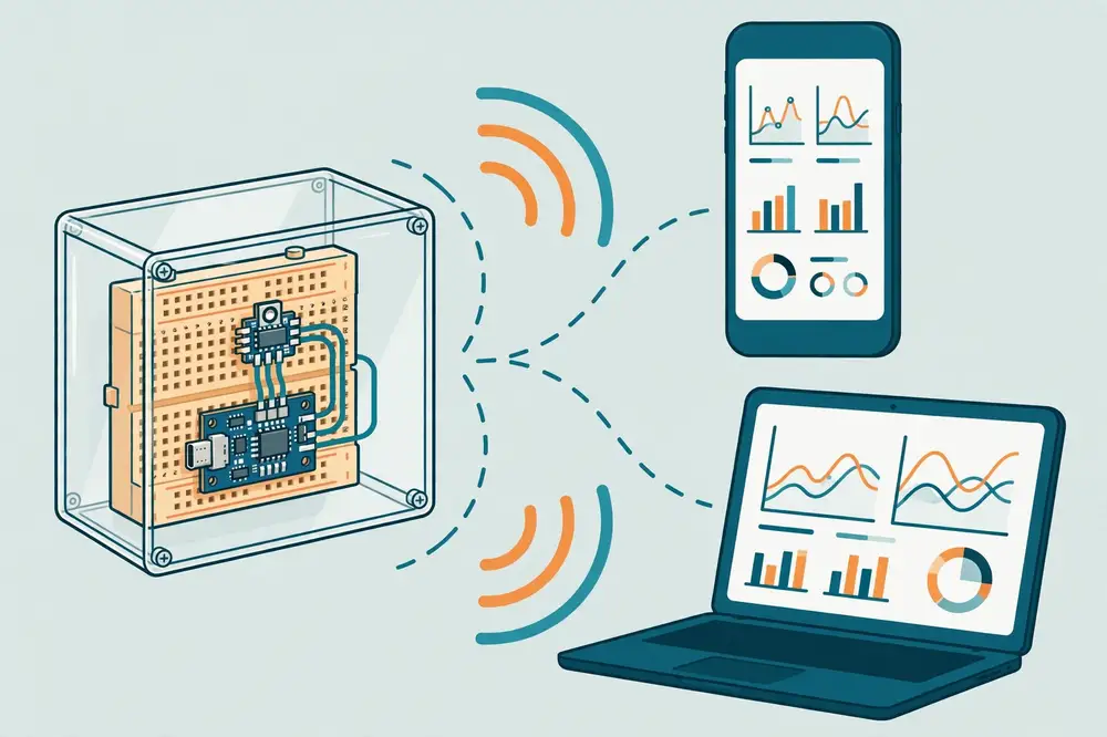
WiFi, HTTPClient-style built-ins and esp_sleep.h ship with the ESP32 core — no install needed.Write the exact version numbers in your lab notes now; you will publish them with your results.
| DHT22 module | ESP32 |
|---|---|
| VCC (+) | 3V3 |
| DATA | GPIO 15 |
| GND (−) | GND |
No other wiring. Keep the sensor a few centimeters from the ESP32 module so the chip's warmth does not bias the temperature reading, and keep the assembly ventilated — never sealed airtight with the board.
Read it fully before uploading — every earlier chapter is visible inside it.
// Capstone: Wi-Fi temperature/humidity sensor node with deep sleep + MQTT.
// Cycle: wake -> read DHT22 -> connect Wi-Fi -> publish -> deep sleep 10 min.
// Book 30, AstolixGen Learning Series.

#include <WiFi.h>
#include <PubSubClient.h>
#include "DHT.h"
#include "esp_sleep.h"

// ============ CONFIGURATION (edit these) ============
const char* WIFI_SSID     = "YOUR_WIFI_NAME";
const char* WIFI_PASSWORD = "YOUR_WIFI_PASSWORD";
const char* MQTT_BROKER   = "test.mosquitto.org";   // use your own broker for real work
const int   MQTT_PORT     = 1883;
const char* TOPIC_BASE    = "astolixgen/capstone/node1";  // YOUR OWN unique prefix
const char* FIRMWARE_VERSION = "1.0";

#define DHTPIN  15
#define DHTTYPE DHT22

#define uS_TO_S_FACTOR 1000000ULL
#define SLEEP_SECONDS  600          // 10 minutes (use 30 for bench testing)
// =====================================================

DHT dht(DHTPIN, DHTTYPE);
WiFiClient espClient;
PubSubClient mqtt(espClient);

// Survives deep sleep: counts total wake cycles.
RTC_DATA_ATTR int bootCount = 0;

bool connectWiFi() {
  WiFi.mode(WIFI_STA);
  WiFi.begin(WIFI_SSID, WIFI_PASSWORD);
  Serial.print("Wi-Fi connecting");
  int attempts = 0;
  while (WiFi.status() != WL_CONNECTED && attempts < 40) {
    delay(500); Serial.print("."); attempts++;
  }
  Serial.println();
  if (WiFi.status() != WL_CONNECTED) {
    Serial.println("Wi-Fi FAILED.");
    return false;
  }
  Serial.print("Wi-Fi OK, IP=");
  Serial.println(WiFi.localIP());
  return true;
}

bool connectMQTT() {
  mqtt.setServer(MQTT_BROKER, MQTT_PORT);
  String clientId = "capstone-" + String((uint32_t)ESP.getEfuseMac(), HEX);
  int attempts = 0;
  while (!mqtt.connected() && attempts < 3) {
    Serial.print("MQTT connecting...");
    if (mqtt.connect(clientId.c_str())) { Serial.println("OK"); return true; }
    Serial.print("failed rc=");
    Serial.println(mqtt.state());
    attempts++;
    delay(2000);
  }
  return mqtt.connected();
}

void publishReading(float tempC, float humidity, int rssi) {
  char topic[96], payload[160];

  // One JSON document per cycle: self-describing and archivable.
  snprintf(payload, sizeof(payload),
           "{\"node\":\"node1\",\"fw\":\"%s\",\"boot\":%d,"
           "\"temperature\":%.1f,\"humidity\":%.1f,\"rssi\":%d}",
           FIRMWARE_VERSION, bootCount, tempC, humidity, rssi);

  snprintf(topic, sizeof(topic), "%s/data", TOPIC_BASE);
  mqtt.publish(topic, payload);
  Serial.print("Published to ");
  Serial.print(topic);
  Serial.print(": ");
  Serial.println(payload);
}

void goToSleep() {
  Serial.print("Sleeping ");
  Serial.print(SLEEP_SECONDS);
  Serial.println(" s...");
  Serial.flush();
  WiFi.disconnect(true);   // cleanly drop Wi-Fi before sleeping
  esp_sleep_enable_timer_wakeup(SLEEP_SECONDS * uS_TO_S_FACTOR);
  esp_deep_sleep_start();
}

void setup() {
  Serial.begin(115200);
  delay(1000);
  bootCount++;

  Serial.println("\n===== Sensor node boot =====");
  Serial.print("Firmware v"); Serial.println(FIRMWARE_VERSION);
  Serial.print("Boot count: "); Serial.println(bootCount);
  Serial.print("Wake cause: ");
  Serial.println(esp_sleep_get_wakeup_cause() == ESP_SLEEP_WAKEUP_TIMER
                 ? "timer" : "power-on");

  dht.begin();

  // 1. Sense first (works even if the network is down).
  delay(2000);  // DHT22 minimum interval
  float h = dht.readHumidity();
  float t = dht.readTemperature();
  if (isnan(h) || isnan(t)) {
    Serial.println("DHT read failed! Sleeping and retrying next cycle.");
    goToSleep();   // never hang on a bad sensor read
  }

  // 2. Connect and publish; skip gracefully if the network fails.
  if (connectWiFi() && connectMQTT()) {
    mqtt.loop();
    publishReading(t, h, WiFi.RSSI());
    delay(500);          // let the publish flush
  } else {
    Serial.println("Network unavailable; reading discarded, will retry.");
  }

  // 3. Sleep.
  goToSleep();
}

void loop() {
  // Never reached: each wake reboots into setup().
}
while(!connected) would drain the battery retrying into a dead network.RTC_DATA_ATTR boot counter. Survives deep sleep; a gap in the sequence at the subscriber tells you exactly how many cycles were lost.SLEEP_SECONDS to 30 while verifying, then 600 for deployment. Never deploy untested firmware.===== Sensor node boot =====
Firmware v1.0
Boot count: 1
Wake cause: power-on
Wi-Fi connecting.........
Wi-Fi OK, IP=192.168.1.42
MQTT connecting...OK
Published to astolixgen/capstone/node1/data: {"node":"node1","fw":"1.0","boot":1,"temperature":27.8,"humidity":54.2,"rssi":-61}
Sleeping 30 s...
===== Sensor node boot =====
Firmware v1.0
Boot count: 2
Wake cause: timer
Wi-Fi connecting.......
Wi-Fi OK, IP=192.168.1.42
MQTT connecting...OK
Published to astolixgen/capstone/node1/data: {"node":"node1","fw":"1.0","boot":2,"temperature":27.9,"humidity":54.0,"rssi":-63}
Sleeping 30 s...
YOUR_PREFIX/# on the broker — JSON documents arrive every cycle.For your research: This capstone is a complete, defensible research instrument. A methodology section writes itself: hardware table (module, board, sensor, GPIO map), firmware environment (IDE/core/library versions), sampling regime (10-min duty cycle, JSON schema), network path (MQTT topic tree, broker), and validation (24-h bench test, RSSI survey, stimulus-response check). Archive the firmware file and a sample of raw MQTT payloads in a repository with a DOI (e.g., Zenodo) and cite it — that single act elevates the work from "student project" to reproducible research artifact.
A running node is the beginning, not the end. After a week of 10-minute cycles you have ~1,000 JSON documents — enough for real analysis:
timestamp,node,fw,boot,temperature,humidity,rssi).This pipeline — collect, validate completeness, visualize, summarize, compare — is the same shape as any experimental science. The hardware was just the instrument.
Project: Wi-Fi temp/humidity node (Book 30 capstone)
Date: ________    Builder: ________
Board: ________ (module: ________)   USB-serial chip: ________
Sensor: DHT22 (module/bare: ________)   DATA pin: GPIO __
IDE version: ________   ESP32 core: ________
Libraries: DHT ______ / Unified Sensor ______ / PubSubClient ______
Wi-Fi: SSID ________ (2.4 GHz confirmed: Y/N)   Broker: ________
Topic prefix: ________   Sleep interval: ________ s
Bench test: __ cycles, __ received, __ boot gaps, RSSI @site: __ dBm
Firmware file archived as: ________________  Version: ____
Issues encountered: ________________________________________
| Item | Approx. cost (USD) |
|---|---|
| ESP32 devkit board | 4–8 |
| DHT22 module | 3–5 |
| Breadboard + jumper wires | 3–5 |
| USB cable + power source | 3–6 |
| Total per node | ~15–25 |
At that price, a 20-node field deployment costs less than a single commercial data logger — the economic argument that makes ESP32-based sensing fundable, and worth stating in proposals.
Key takeaways: - The canonical node architecture: wake → sense → connect → publish self-describing JSON → deep sleep, with bounded retries and no hang states. - Every payload should carry node ID, firmware version, boot count, and RSSI — auditable data needs no external notes. - Verify end to end: subscriber check, boot-count continuity, physical stimulus, 24-h power test, RSSI survey. - Harden for the field: ventilated enclosure, measured power budget, private broker, OTA plan, archived firmware + versions.
| Pin group (typical GPIO numbers) | Notes |
|---|---|
| GPIO 32–39 | ADC1 analog inputs — safe for sensors even with Wi-Fi on. 34–39 are input-only (no digitalWrite). |
| GPIO 25, 26, 27, 14, 12, 13 | General-purpose digital I/O; DAC on 25/26. |
| GPIO 15, 2, 4, 5, 18, 19, 21, 22, 23 | General digital I/O on most boards (2 is often the built-in LED; 21/22 are the default I2C bus). |
| GPIO 0, 12, 15, 2, 4 | Strapping pins — sampled at boot; avoid holding them HIGH/LOW externally during reset, or the board may fail to boot. GPIO 0 doubles as the BOOT button. |
| GPIO 6–11 | Connected to the on-board flash — do not use. |
| ADC2 pins (various) | Analog reads conflict with Wi-Fi — avoid for sensors in networked projects. |
Rule of thumb for beginners: if you need "just a pin," GPIO 15, 4, 5, 18, or 19 are boring in the best way. When in doubt, consult your specific board's pinout diagram — manufacturers differ.
| Symptom | Most likely cause | Fix (chapter) |
|---|---|---|
Timed out waiting for packet header at upload |
Board not in download mode | Hold BOOT during Connecting... (3, 11) |
| No port in Tools → Port | Charge-only cable / missing driver | Swap cable; install CP210x/CH340 driver (2, 11) |
⸮⸮⸮ in Serial Monitor |
Baud mismatch | Set monitor to 115200 (3, 11) |
| Repeating boot text, sketch never runs | Crash in setup() (null pointer, stack overflow) |
Read crash dump; bisect setup() (11) |
Brownout detector was triggered |
Weak supply vs. Wi-Fi current spikes | Stronger supply / shorter cable (11) |
| Phantom button triggers | Floating input | INPUT_PULLUP; check GND wire (4, 11) |
| One press counts many | Contact bounce | 50 ms debounce; count edges (4) |
Failed to read from DHT sensor! |
Wrong type/pin/interval/wiring | Check DHTTYPE, pin, 2 s interval (5, 11) |
| Analog stuck at 0/4095 or Wi-Fi drift | Over-range input or ADC2 pin | Multimeter check; move to ADC1 (5, 11) |
| Wi-Fi dots forever | Wrong credentials / 5 GHz / WPA3 / captive portal | Verify; test with phone hotspot (6, 11) |
| Wi-Fi connects then drops | Weak RSSI or brownout | Survey RSSI; fix power (6, 9, 11) |
MQTT rc=-2 loop |
Broker unreachable | Test broker from another device (7, 11) |
| MQTT drops every ~15 s | client.loop() starved |
Replace long delay() with millis() timing (7) |
| HTTP code −1 | No route / DNS failure | Check Wi-Fi; test URL on desktop (8) |
| HTTP 4xx codes | Wrong URL / headers / malformed JSON | Print exact payload; fix per code table (8) |
| Deep sleep never wakes | Timer not armed before esp_deep_sleep_start() |
Arm → flush → start order (9) |
| Serial cut off before sleep | UART buffer discarded | Serial.flush() before sleeping (9) |
| No OTA network port in IDE | Different subnet / firewall / Wi-Fi failed | Same subnet; check firewall; verify Wi-Fi (10) |
| "Worked yesterday, changed nothing" | Loose wire / dying battery / router change | Re-seat wiring; re-run blink test (11) |
| Library | Author | Used in | Notes |
|---|---|---|---|
| DHT sensor library | Adafruit | Ch. 5, 12 | Accept the Adafruit Unified Sensor dependency |
| PubSubClient | Nick O'Leary | Ch. 7, 12 | The standard Arduino MQTT client |
| ArduinoJson | Benoît Blanchon | (next step) | For complex JSON payloads beyond snprintf |
WiFi, HTTPClient, ArduinoOTA, esp_sleep.h |
Espressif (built into core) | Ch. 6, 8, 9, 10 | No install needed — part of the ESP32 core |
{"key": value}) for structuring data sent to servers.INPUT_PULLUP.RTC_DATA_ATTR for counters.Serial.print.setup() + loop()).site/room/measurement); + and # are wildcards.millis(). Average five tries.seconds,humidity,temperature) every 5 seconds. Copy 10 minutes of output into a spreadsheet and plot temperature over time. Breathe on the sensor mid-run and mark the event..../led) that turns the built-in LED on/off from your phone — your first bidirectional IoT control.[1] Espressif Systems, "ESP32 Series Datasheet," Espressif Systems, Shanghai, China. [Online]. Available: https://www.espressif.com/en/support/download/documents
[2] Espressif Systems, "ESP32 Technical Reference Manual," Espressif Systems, Shanghai, China. [Online]. Available: https://www.espressif.com/en/support/download/documents
[3] Espressif Systems, "Arduino-ESP32 Official Documentation," GitHub. [Online]. Available: https://github.com/espressif/arduino-esp32
[4] Espressif Systems, "ESP-IDF Programming Guide," Espressif Systems. [Online]. Available: https://docs.espressif.com/projects/esp-idf/en/latest/
[5] Arduino, "Arduino IDE 2 Documentation," Arduino. [Online]. Available: https://docs.arduino.cc/software/ide/
[6] A. Banks and R. Gupta, Eds., "MQTT Version 3.1.1," OASIS Standard, 2014. [Online]. Available: https://docs.oasis-open.org/mqtt/mqtt/v3.1.1/mqtt-v3.1.1.html
[7] MQTT.org, "MQTT: The Standard for IoT Messaging," OASIS / Eclipse Foundation. [Online]. Available: https://mqtt.org/
[8] N. O'Leary, "PubSubClient — Arduino Client for MQTT," GitHub. [Online]. Available: https://github.com/knolleary/pubsubclient
[9] Adafruit Industries, "DHT Sensor Library," GitHub. [Online]. Available: https://github.com/adafruit/DHT-sensor-library
[10] R. T. Fielding, "Architectural Styles and the Design of Network-based Software Architectures," Ph.D. dissertation, Univ. California, Irvine, CA, USA, 2000. [Online]. Available: https://www.ics.uci.edu/~fielding/pubs/dissertation/top.htm
End of Book 30. Next: Book 31.